


Modes of Operation
8-24
ADSP-BF59x Blackfin Processor Hardware Reference
In
WDTH_CAP
mode, the
TMR
pin is an input pin. The internally clocked
timer is used to determine the period and pulse width of externally applied
rectangular waveforms. Setting the
TMODE
field to b#10 in the
TIMER_CONFIG
register enables this mode.
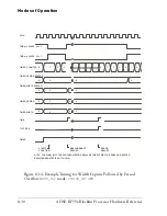
When enabled in this mode, the timer resets the count in the
TIMER_COUNTER
register to 0x0000 0001 and does not start counting until
it detects a leading edge on the
TMR
pin.
When the timer detects the first leading edge, it starts incrementing.
When it detects a trailing edge of a waveform, the timer captures the cur-
rent 32-bit value of the
TIMER_COUNTER
register into the width buffer. At
the next leading edge, the timer transfers the current 32-bit value of the
TIMER_COUNTER
register into the period buffer. The count register is reset
to 0x0000 0001 again, and the timer continues counting and capturing
until it is disabled.
In this mode, software can measure both the pulse width and the pulse
period of a waveform. To control the definition of leading edge and trail-
ing edge of the
TMR
pin, the
PULSE_HI
bit in the
TIMER_CONFIG
register is
set or cleared. If the
PULSE_HI
bit is cleared, the measurement is initiated
by a falling edge, the content of the counter register is captured to the
pulse width buffer on the rising edge, and to the period buffer on the next
falling edge. When the
PULSE_HI
bit is set, the measurement is initiated by
a rising edge, the counter value is captured to the pulse width buffer on
the falling edge, and to the period buffer on the next rising edge.
In
WDTH_CAP
mode, these three events always occur at the same time:
1. The
TIMER_PERIOD
register is updated from the period buffer.
2. The
TIMER_WIDTH
register is updated from the width buffer.
3. The
TIMIL
bit gets set (if enabled) but does not generate an error.
The
PERIOD_CNT
bit in the
TIMER_CONFIG
register controls the point in
time at which this set of transactions is executed. Taken together, these
Summary of Contents for ADSP-BF59x Blackfin
Page 64: ...Development Tools 1 22 ADSP BF59x Blackfin Processor Hardware Reference...
Page 74: ...Processor Specific MMRs 2 10 ADSP BF59x Blackfin Processor Hardware Reference...
Page 244: ...Programming Examples 6 40 ADSP BF59x Blackfin Processor Hardware Reference...
Page 700: ...Programming Examples 16 78 ADSP BF59x Blackfin Processor Hardware Reference...
Page 738: ...Boundary Scan Architecture B 8 ADSP BF59x Blackfin Processor Hardware Reference...