


ADSP-BF59x Blackfin Processor Hardware Reference
11-9
UART Port Controllers
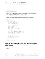
periods out of 16 clock periods in the cycle. The pulse is centered around
the middle of the bit time, as shown in
Figure 11-3
. The final IrDA pulse
is fed to the off-chip infrared driver.
This modulation approach ensures a pulse width output from the UART
of three cycles high out of every 16 UART clock cycles. As shown in
Table 11-1 on page 11-13
, the error terms associated with the bit rate gen-
erator are very small and well within the tolerance of most infrared
transceiver specifications.
IrDA Receive Operation
The IrDA receiver function is more complex than the transmit function.
The receiver must discriminate the IrDA pulse and reject noise. To do
this, the receiver looks for the IrDA pulse in a narrow window centered
around the middle of the expected pulse.
Glitch filtering is accomplished by counting 16 system clocks from the
time an initial pulse is seen. If the pulse is absent when the counter
expires, it is considered a glitch. Otherwise, it is interpreted as a 0. This is
acceptable because glitches originating from on-chip capacitive cross-cou-
pling typically do not last for more than a fraction of the system clock
period. Sources outside of the chip and not part of the transmitter can be
avoided by appropriate shielding. The only other source of a glitch is the
Figure 11-3. IrDA Transmit Pulse
0
1
0
8/16
9/16
7/16
16/16
NRZ
INVERTED
FINAL
IrDA
8/16
9/16
7/16
16/16
Summary of Contents for ADSP-BF59x Blackfin
Page 64: ...Development Tools 1 22 ADSP BF59x Blackfin Processor Hardware Reference...
Page 74: ...Processor Specific MMRs 2 10 ADSP BF59x Blackfin Processor Hardware Reference...
Page 244: ...Programming Examples 6 40 ADSP BF59x Blackfin Processor Hardware Reference...
Page 700: ...Programming Examples 16 78 ADSP BF59x Blackfin Processor Hardware Reference...
Page 738: ...Boundary Scan Architecture B 8 ADSP BF59x Blackfin Processor Hardware Reference...