


ADSP-BF59x Blackfin Processor Hardware Reference
15-11
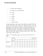
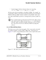
Parallel Peripheral Interface
Note the VBI is split into two regions within each field. From the PPI’s
standpoint, it considers these two separate regions as one contiguous
space. However, keep in mind that frame synchronization begins at the
start of field 1, which doesn’t necessarily correspond to the start of vertical
blanking. For instance, in 525/60 systems, the start of field 1 (
F
= 0) cor-
responds to line 4 of the VBI.
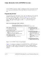
ITU-R 656 Output Mode
The PPI does not explicitly provide functionality for framing an ITU-R
656 output stream with proper preambles and blanking intervals. How-
ever, with the TX mode with 0 frame syncs, this process can be supported
manually. Essentially, this mode provides a streaming operation from
memory out through the PPI. Data and control codes can be set up in
memory prior to sending out the video stream. With the 2D DMA
engine, this could be performed in a number of ways. For instance, one
line of blanking (
H
+
V
) could be stored in a buffer and sent out N times by
the DMA controller when appropriate, before proceeding to DMA active
video. Alternatively, one entire field (with control codes and blanking) can
be set up statically in a buffer while the DMA engine transfers only the
active video region into the buffer, on a frame-by-frame basis.
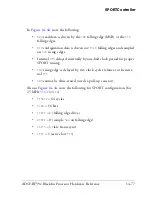
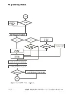
Frame Synchronization in ITU-R 656 Modes
Synchronization in ITU-R 656 modes always occurs at the falling edge
of
F
, the field indicator. This corresponds to the start of field 1. Conse-
quently, up to two fields might be ignored (for example, if field 1 just
started before the PPI-to-camera channel was established) before data is
received into the PPI.
Because all
H
and
V
signaling is embedded in the datastream in ITU-R 656
modes, the
PPI_COUNT
register is not necessary. However, the
PPI_FRAME
register is used in order to check for synchronization errors. The user pro-
grams this MMR for the number of lines expected in each frame of video,
and the PPI keeps track of the number of EAV-to-SAV transitions that
Summary of Contents for ADSP-BF59x Blackfin
Page 64: ...Development Tools 1 22 ADSP BF59x Blackfin Processor Hardware Reference...
Page 74: ...Processor Specific MMRs 2 10 ADSP BF59x Blackfin Processor Hardware Reference...
Page 244: ...Programming Examples 6 40 ADSP BF59x Blackfin Processor Hardware Reference...
Page 700: ...Programming Examples 16 78 ADSP BF59x Blackfin Processor Hardware Reference...
Page 738: ...Boundary Scan Architecture B 8 ADSP BF59x Blackfin Processor Hardware Reference...