


Specific Boot Modes
16-42
ADSP-BF59x Blackfin Processor Hardware Reference
Similarly, the boot kernel uses the standard 0x03 SPI read command, by
default.
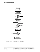
SPI Device Detection Routine
Because
BMODE
= 010 or 100 supports booting from various SPI memories,
the boot kernel automatically detects what type of memory is connected.
To determine whether the SPI memory device requires an 8-, 16-, 24- or
32-bit addressing scheme, the boot kernel performs a device detection
sequence prior to booting. The
MISO
signal requires a pull-up resistor,
since the routine relies on the fact that memories do not drive their data
outputs unless the right number of address bytes are received.
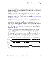
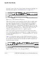
Initially, the boot kernel transmits a read command (either 0x03 or 0x0B)
on the
MOSI
line, which is immediately followed by two zero bytes. Once
the transmission is finished, the boot kernel interrogates the data received
on the
MISO
line. If it does not equal 0xFF (usually a
DMACODE
value of
0x01 is expected), then an 8-bit addressable device is assumed.
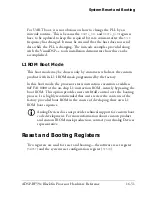
If the received value equals 0xFF, it is assumed that the memory device has
not driven its data output yet and that the 0xFF value is due to the pull-up
resistor. Thus, another zero byte is transmitted and the received data is
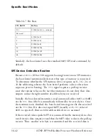
Table 16-7. Bit Rate
SPI_BAUD
Bit Rate
133
SCLK/(2x133) << default
Reserved
2
SCLK/(2x2)
4
SCLK/(2x4)
8
SCLK/(2x8)
16
SCLK/(2x16)
32
SCLK/(2x32)
64
SCLK/(2x64)
Summary of Contents for ADSP-BF59x Blackfin
Page 64: ...Development Tools 1 22 ADSP BF59x Blackfin Processor Hardware Reference...
Page 74: ...Processor Specific MMRs 2 10 ADSP BF59x Blackfin Processor Hardware Reference...
Page 244: ...Programming Examples 6 40 ADSP BF59x Blackfin Processor Hardware Reference...
Page 700: ...Programming Examples 16 78 ADSP BF59x Blackfin Processor Hardware Reference...
Page 738: ...Boundary Scan Architecture B 8 ADSP BF59x Blackfin Processor Hardware Reference...