


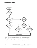


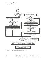


Interface Overview
7-4
ADSP-BF59x Blackfin Processor Hardware Reference
Port G Structure
Table 7-2 on page 7-4
shows the multiplexer scheme for port G. Port G
is controlled by the
PORTG_MUX
and
PORTG_FER
registers.
Port G consists of 16 pins, referred to as
PG0
to
PG15
, as shown in
Table 7-2
.
Any GPIO can be enabled individually and overrides the peripheral func-
tion if the respective bit in the
PORTG_FER
register is cleared.
Bit 11
UART0TX
SPI0SSEL4
PF11
Bit 12
UART0RX
SPI0SSEL7
TACI2–0
PF12
Bit 13
SPI0MOSI
SPI1SSEL3
PF13
Bit 14
SPI0MISO
SPI1SSEL4
PF14
Bit 15
SPI0CLK
SPI1SSEL5
PF15
Table 7-2. Port G Multiplexing Scheme
PORTG_MUX
0
1
1st function
2nd function
Additional Use
GPIO
Bit 0
DR0SEC
SPI0SSEL1
SPI0SS
PG0
Bit 1
DR0PRI
SPI1SSEL1
WAKEN3
PG1
Bit 2
RSCLK0
SPI0SSEL5
PG2
Bit 3
RFS0
PPI_FS3
PG3
Bit 4
DT0SEC
SPI0SSEL6
PG4
/
HWAIT
Bit 5
DT0PRI
SPI1SSEL6
PG5
Bit 6
TSCLK0
Reserved
PG6
Bit 7
TFS0
SPI1SSEL7
PG7
Table 7-1. Port F Multiplexing Scheme (Continued)
PORTF_MUX
0
1
1st function
2nd function
Additional Use
GPIO
Summary of Contents for ADSP-BF59x Blackfin
Page 64: ...Development Tools 1 22 ADSP BF59x Blackfin Processor Hardware Reference...
Page 74: ...Processor Specific MMRs 2 10 ADSP BF59x Blackfin Processor Hardware Reference...
Page 244: ...Programming Examples 6 40 ADSP BF59x Blackfin Processor Hardware Reference...
Page 700: ...Programming Examples 16 78 ADSP BF59x Blackfin Processor Hardware Reference...
Page 738: ...Boundary Scan Architecture B 8 ADSP BF59x Blackfin Processor Hardware Reference...