


Functional Description
15-20
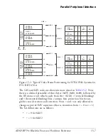
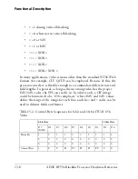
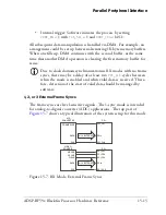
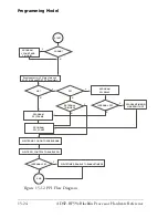
ADSP-BF59x Blackfin Processor Hardware Reference
state of
PPI_FS1
and/or
PPI_FS2
, so
PPI_FS3
has no inherent
programmability.
To program
PPI_FS1
and/or
PPI_FS2
for operation in an internal
frame sync mode:
1. Configure and enable DMA for the PPI. See
“DMA Operation” on
page 15-22
.
2. Configure the width and period for each frame sync signal via the
appropriate
TIMER_WIDTH
and
TIMER_PERIOD
registers.
3. Set up the appropriate
TIMER_CONFIG
register(s) for
PWM_OUT
mode.
This includes setting
CLK_SEL
to 1 and
TIN_SEL
to 1 for each timer
involved.
4. Write to
PPI_CONTROL
to configure and enable the PPI.
5. Write to
TIMER_ENABLE
to enable the appropriate timer(s).
It is important to guarantee proper frame sync polarity between the
PPI and timer peripherals. To do this, make sure that if
PPI_CONTROL[15:14]
= b#10 or b#11, the
PULSE_HI
bit is cleared in
the appropriate
TIMER_CONFIG
register(s). Likewise, if
PPI_CONTROL[15:14]
= b#00 or b#01, the
PULSE_HI
bit should be
set in the appropriate
TIMER_CONFIG
register(s).
To switch to another PPI mode not involving internal frame syncs:
1. Disable the PPI (using
PPI_CONTROL
).
2. Disable the appropriate timer(s) (using
TIMER_DISABLE
).
Modes With External Frame Syncs
In RX modes with external frame syncs, the
PPI_FS1
and
PPI_FS2
pins
become edge-sensitive inputs. In such modes the timers associated with
the
PPI_FS1
and
PPI_FS2
pins can still be used for a purpose not involving
the actual pin. However, timer access to a
TMRx
pin is disabled when the
Summary of Contents for ADSP-BF59x Blackfin
Page 64: ...Development Tools 1 22 ADSP BF59x Blackfin Processor Hardware Reference...
Page 74: ...Processor Specific MMRs 2 10 ADSP BF59x Blackfin Processor Hardware Reference...
Page 244: ...Programming Examples 6 40 ADSP BF59x Blackfin Processor Hardware Reference...
Page 700: ...Programming Examples 16 78 ADSP BF59x Blackfin Processor Hardware Reference...
Page 738: ...Boundary Scan Architecture B 8 ADSP BF59x Blackfin Processor Hardware Reference...