


44
Wiring
Section 3-4
To avoid such noise-generated operational errors and improve system reliabil-
ity, always observe the following precautions in wiring the system.
Be sure to use the sizes and materials indicated in the specifications when
connecting power lines and cables.
Power lines (e.g., AC power supply, motor power line) and control lines (e.g.,
pulse output lines, external I/O signal lines) must be wired separately. Never
put these lines into the same duct or make them into a single bundle.
• Attach a multi-layer ceramic capacitor of a thickness of less than 1
µ
F to
the pulse output power supply to improve noise resistance.
• Do not use a 24-VDC or 5-VDC power supply for pulse output in common
with the power supply for other I/O.
• Use shielded cable for control lines.
• Connect the shielded cable to the frame ground at both the PCU and the
driver.
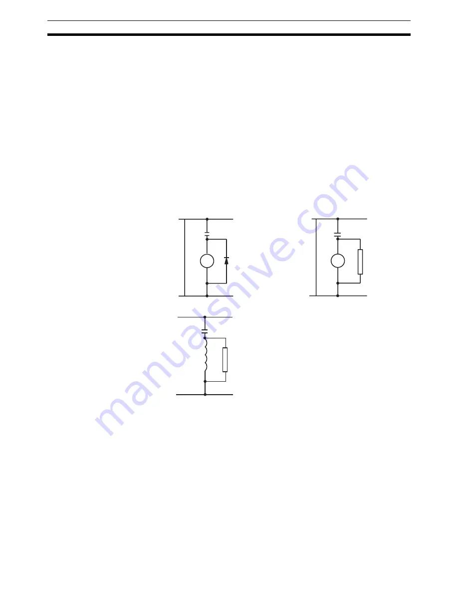
• Attach a surge absorber to all inductive loads, such as relays, solenoids,
and solenoid valves.
Note
Connect the diode and surge absorber as close as possible to the relay. Use a
diode capable of withstanding a voltage five times higher than the circuit volt-
age.
• Insert a noise filter into the power supply inlet if noise enters the power
line (e.g., when it is connected to the same power supply as an electric
welder or an electric spark machine or when there is any supply generat-
ing high frequency noise).
• Connect to a ground of 100
Ω
or less and use the thickest possible wire,
greater than 1.25 mm
2
.
• Twisted-pair cable is recommended for power lines.
+
DC
–
Diode for surge
absorption
AC
Surge
absorber
RY
RY
DC relays
AC relays
Solenoid
Surge absorber
Solenoids, etc.
Summary of Contents for CS1W-213 - REV 02-2008
Page 2: ...CS1W NC113 213 413 133 233 433 Position Control Units Operation Manual Revised February 2008 ...
Page 3: ...iv ...
Page 13: ...xiv ...
Page 15: ...xvi ...
Page 19: ...xx ...
Page 43: ...18 Basic Operational Flow Section 2 1 ...
Page 87: ...62 Servo Relay Unit Section 3 7 ...
Page 199: ...174 Z phase Margin Section 6 8 ...
Page 217: ...192 Sample Program Section 7 7 ...
Page 285: ...260 Easy Backup Function Ver 2 0 or later Section 9 11 ...
Page 377: ...352 Common Parameter Area Appendix C ...


