


186
Acceleration/Deceleration
Section 7-6
Next Command
• Position
• Speed, V
2
(pps)
Note
When the designations for the next positioning operation are given during
operation, T
2
and T
3
are calculated using the acceleration time Ta and decel-
eration time Td specified at the time operation started from the stopped posi-
tion. It is not necessary to specify new acceleration and deceleration times.
Case 2: Speed for the Next Positioning Operation is Slower
In this case (V
1
>
V
2
), the calculations will be the same as before except for T
2
,
which is determined according to the following equation.
Actual acceleration time T
2
= (V
1
– V
2
)/(V
MAX
– V
0
)
×
Td
7-6-3
Calculation of Acceleration/Deceleration Times when the Speed
is Changed During Operation
If the speed or the override setting is changed during direct operation, the
motor will be accelerated or decelerated to the new speed. The actual accel-
eration and deceleration times for this kind of operation can be calculated in
the way shown below.
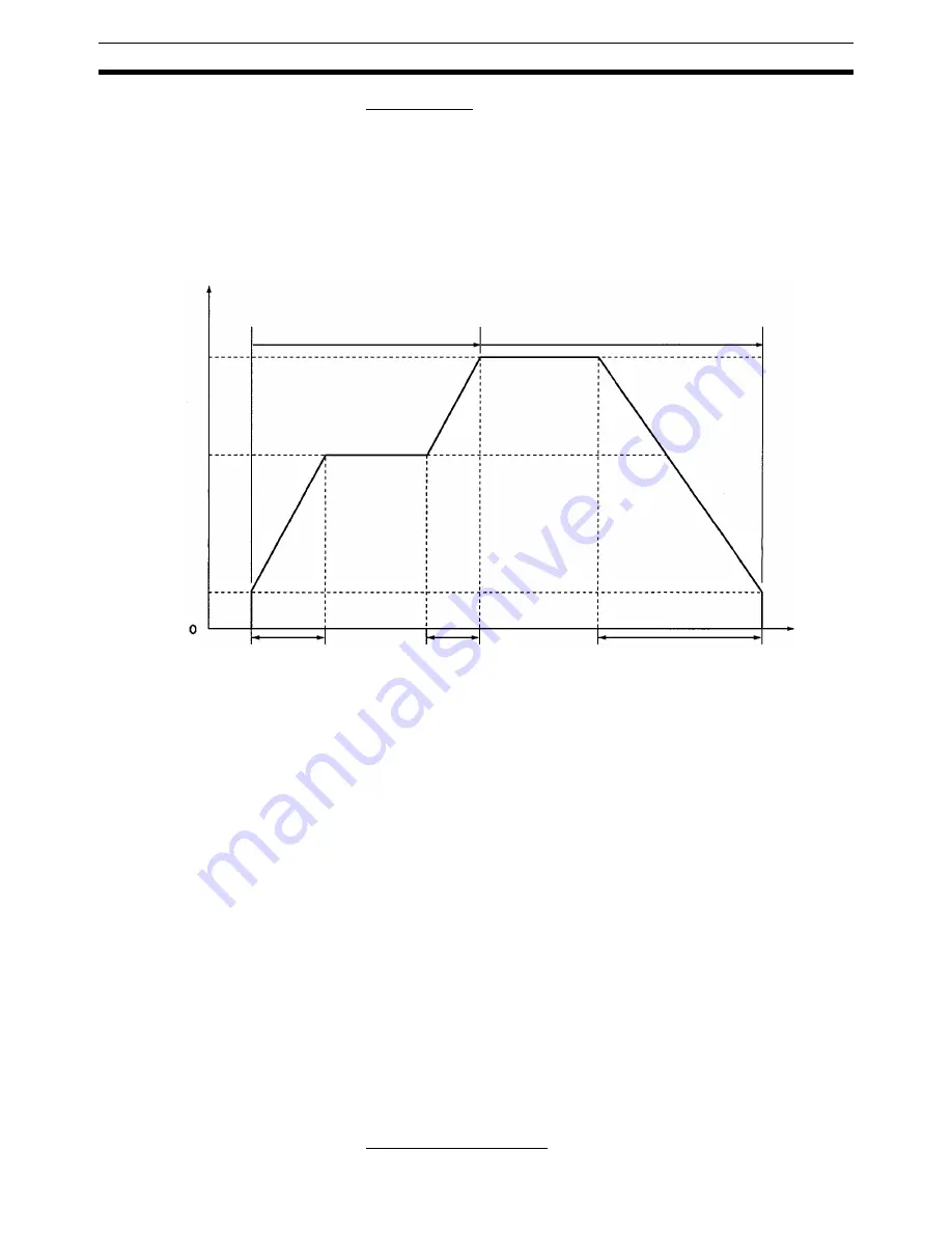
Case 1: Next Speed is Faster
Actual acceleration time, T
1
= (V
1
– V
0
)/(V
MAX
– V
0
)
×
Ta
Actual acceleration time, T
2
= (V
2
– V
1
)/(V
MAX
– V
0
)
×
Ta
Actual deceleration time, T
3
= (V
2
– V
0
)/(V
MAX
– V
0
)
×
Td
• The following axis parameter settings are used:
• Maximum speed, V
MAX
(pps)
• Initial speed, V
0
(pps)
• The following operating data area settings are also used:
First Positioning Operation
Speed
Speed V
2
Speed V
1
Initial speed V
0
Actual
acceleration
time T
1
Actual
acceleration
time T
2
Actual
deceleration
time T
3
Time
First positioning operation
Next positioning operation
Summary of Contents for CS1W-213 - REV 02-2008
Page 2: ...CS1W NC113 213 413 133 233 433 Position Control Units Operation Manual Revised February 2008 ...
Page 3: ...iv ...
Page 13: ...xiv ...
Page 15: ...xvi ...
Page 19: ...xx ...
Page 43: ...18 Basic Operational Flow Section 2 1 ...
Page 87: ...62 Servo Relay Unit Section 3 7 ...
Page 199: ...174 Z phase Margin Section 6 8 ...
Page 217: ...192 Sample Program Section 7 7 ...
Page 285: ...260 Easy Backup Function Ver 2 0 or later Section 9 11 ...
Page 377: ...352 Common Parameter Area Appendix C ...


