


250
Backlash Compensation
Section 9-8
Example 4: Origin adjustment command output turned ON in operating mode 3 (only while pulses
stopped)
9-8
Backlash Compensation
9-8-1
Outline of Operation
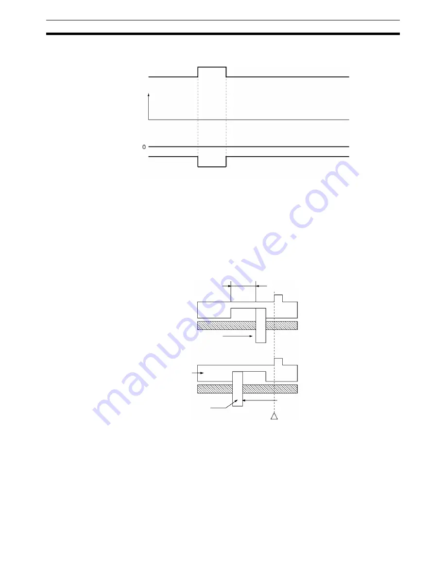
“Backlash” means the play between the driving axis and the mechanical sys-
tem being driven. If there is backlash in positioning from the positive or nega-
tive direction it will cause a discrepancy of the same magnitude in the
positioning. Backlash compensation is used to make this discrepancy as
small as possible.
In the above diagram, after positioning from the positive side, backlash is
compensated for up to the amount of the output of pulses set for the backlash
compensation either when positioning in the negative direction or when the
positioning direction (pulse output direction) is reversed.
With this PCU, the backlash compensation and backlash compensation
speed can be designated by parameters.
The backlash compensation operation is used after the origin has been estab-
lished. If the backlash compensation speed is set to “0,” compensatory output
is made at the initial speed. If the initial speed is below 250 pps, the compen-
satory speed is output at 250 pps.
Pulse output
Speed
Time
Busy Flag
(word n+8, bit 13)
Origin
adjustment
command output
(word n, bit 13)
X-axis origin
adjustment command
output (PCU output
signal)
Backlash
Positioning from positive side:
Position on drive side =
position on driven side
Positioning from
positive side
Driven side
Drive side
Positioning from negative side:
Position on drive side =
position on driven side
−
amount of backlash
compensation
Same position
Positioning from negative side
Summary of Contents for CS1W-213 - REV 02-2008
Page 2: ...CS1W NC113 213 413 133 233 433 Position Control Units Operation Manual Revised February 2008 ...
Page 3: ...iv ...
Page 13: ...xiv ...
Page 15: ...xvi ...
Page 19: ...xx ...
Page 43: ...18 Basic Operational Flow Section 2 1 ...
Page 87: ...62 Servo Relay Unit Section 3 7 ...
Page 199: ...174 Z phase Margin Section 6 8 ...
Page 217: ...192 Sample Program Section 7 7 ...
Page 285: ...260 Easy Backup Function Ver 2 0 or later Section 9 11 ...
Page 377: ...352 Common Parameter Area Appendix C ...


