17 - 6
17. SPEED CONTROL OPERATION
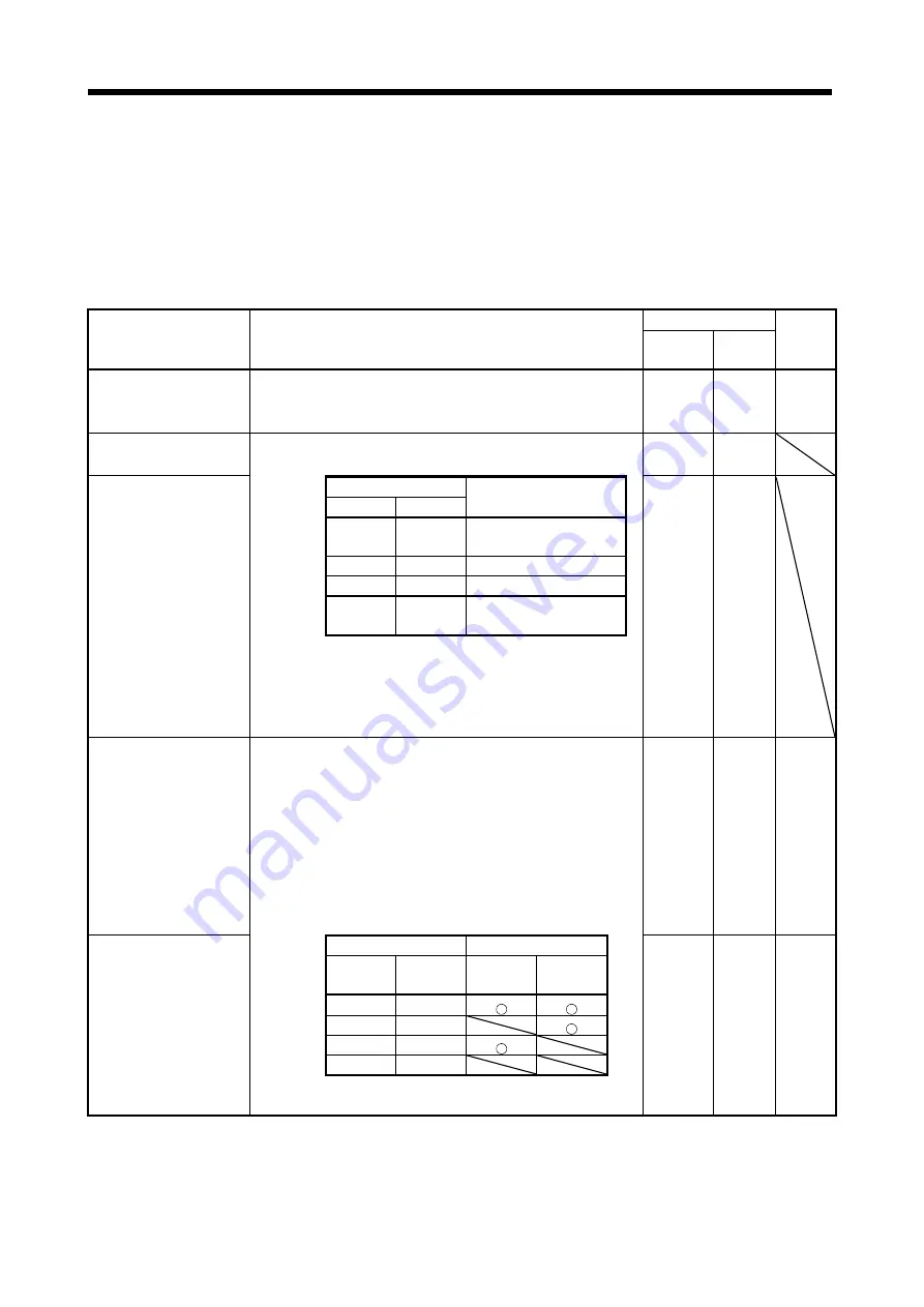
17.2.2 Detailed explanation of I/O signals
(1) Input signals (input devices)
The note signs in the remarks column indicate the following descriptions.
*1: Can be used as an external input signal of CN6 connector by setting parameter No.PD12.
*2: Can be automatically turned on by setting parameter No.PD01.
*3: Can be automatically turned on by setting parameter No.PD03.
The device whose Device No. field has an oblique line cannot be used with CC-Link.
Signal name
(Device name)
Description
Device No.
Remarks
1 station
occupied
2 stations
occupied
Servo-on
Turning RYn0 turns on the base circuit, making operation ready to start.
(Servo on status)
Turning RYn0 off shuts off the base circuit, coasting the servo motor.
(Servo off status)
RYn0 RYn0 *2
Forward rotation start
This is used to start the servo motor.
The following shows the rotation directions.
RYn1 RYn1
Reverse rotation start
(Note) RY of CC-Link
Servo motor starting
direction
RYn2 RYn2
RYn2
RYn1
0 0
Stop (stop when speed
command=0)
0
1
CCW
direction
1
0
CW
direction
1 1
Stop (stop when speed
command=0)
Note.
0:OFF
1:ON
When RYn1 and RYn2 are turned on or off during operation, the servo
motor decelerates to a stop. In this case, the servo will not be locked.
The servo motor speed will be controlled to 0r/min, and the stop
position will not be maintained.
Forward rotation stroke end In factory setting, an external input signal (CN6-3) is enabled for the
forward rotation stroke end, and an external input signal (CN6-4) for the
reverse rotation stroke end.
In operation, short circuit between CN6-3 and DOCOM, and CN6-4 and
DOCOM. When they are opened, the servo motor stops immediately,
and the servo will be locked.
When using with CC-Link, enable the signals with parameter No.PD12.
When operating, turn RYn4 and RYn5 on. When they are turned off,
the servo motor stops immediately, and the servo will be locked. A stop
method is selectable using parameter No.PD20.
When the forward rotation stroke end and reverse rotation stroke end
are not used, set them to "automatic on" by parameter No.PD01.
RYn4 RYn4 *2
Reverse rotation stroke end
(Note) RY of CC-Link
Operation
RYn5
RYn5
*1
RYn4 RYn5
CCW
direction
CW
direction
*2
1
1
0
1
1
0
0
0
Note.
0:OFF
1:ON
Summary of Contents for Melservo-J3 Series MR-J3-B
Page 19: ...10 MEMO ...
Page 55: ...1 36 1 FUNCTIONS AND CONFIGURATION MEMO ...
Page 61: ...2 6 2 INSTALLATION MEMO ...
Page 179: ...4 58 4 SIGNALS AND WIRING MEMO ...
Page 241: ...5 62 5 OPERATION MEMO ...
Page 357: ...10 16 10 SPECIAL ADJUSTMENT FUNCTIONS MEMO ...
Page 385: ...11 28 11 TROUBLESHOOTING MEMO ...
Page 397: ...12 12 12 OUTLINE DRAWINGS MEMO ...
Page 755: ...17 70 17 SPEED CONTROL OPERATION MEMO ...
Page 793: ...App 38 APPENDIX MEMO ...
Page 799: ...MEMO ...


