Brivo OEC 715/785/865/865 Mobile C-Arm X-Ray Product Service Manual
2-14
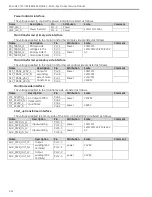
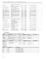
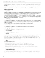
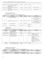
MF_PWR
mainframe power detection
signal
PJ8-8
digital
0/+12V (>6V=High)
PDU_CONNECT_2
connection status signal
from PDU to SIB
PJ8-9
digital
0/+12V (>6V=High)
PDU_CONNECT_1
connection status signal
from PDU to SIB
PJ8-10 digital
0/+12V (>6V=High)
RSRV_FROM_PDU_1
Reserved signal from PDU
PJ8-11 digital
0/+12V (>6V=High)
RSRV_FROM_PDU_2
Reserved signal from PDU
PJ8-12 digital
0/+12V (>6V=High)
RSRV_FROM_PDU_3
Reserved signal from PDU
PJ8-13 digital
0/+12V (>6V=High)
GND
GND
PJ8-14 GND
0V
RSRV_FROM_SIB_1
Reserved signal from SIB
PJ8-15 digital
0/+12V (>6V=High)
RSRV_FROM_SIB_2
Reserved signal from SIB
PJ8-16 digital
0/+12V (>6V=High)
RSRV_FROM_SIB_3
Reserved signal from SIB
PJ8-17 digital
0/+12V (>6V=High)
GND
GND
PJ8-18 GND
0V
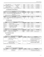
BEEP_INVALID_KEY_C
MD
Invalid key beep command PJ8-19 digital
0/+12V (>6V=High)
INTLC_BOARD
interlock board connection
status signal
PJ8-20 digital
0/+12V (>6V=High)
ACK_PDU2SIB
acknowledge signal
between PDU and SIB
PJ8-21 digital
0/+12V (>6V=High)
SYS_PWR_OFF_CMD
system power off
command
PJ8-22 digital
0/+12V (>6V=High)
SYS_PWR_OFF_DENY
system power off deny
command
PJ8-23 digital
0/+12V (>6V=High)
MF_PWR_ON_CMD
mainframe power on
command
PJ8-24 digital
0/+12V (>6V=High)
RDY
WKS boot up ready
PJ8-25 digital
0/+12V (>6V=High)
BEEP_ERR_CMD
error beep command
PJ8-26 digital
0/+12V (>6V=High)
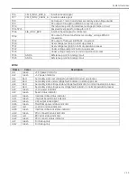
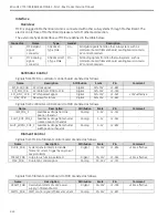
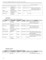
UPS interface
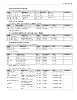
UPS switch on/off control signal interface is shown as follows:
Name
Description
Pin
Attribution Scale
Comment
UPS_OUTPUT UPS output status signal
PJ14-1
Analog
0/10-14VDC
GND
GND
PJ14-2
0
0
ON_BATT
UPS battery/line status signal
PJ14-3
Analog
0/10-14VDC
REMOTE
UPS remote signal
PJ14-4
Digital
3.3V/5V TTL
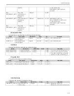
UPS switch off interface in emergency is shown as follows:
Name
Description
Pin
Attribution Scale
Comment
EMERGENCY_
BUTTON_1
UPS EMERGENCY SWICH
OFF BUTTON
PJ15-1
Digital
3.3V/5V TTL
EMERGENCY_
BUTTON_2
PJ15-2
Digital
3.3V/5V TTL
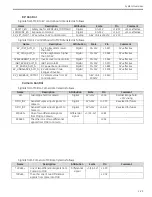
Test Point:
Name
Description
Description
TP1
+12V
+12V power on board
TP2
+24V
+24V power on board
TP3
+5V
+5V power on board
TP4
+3.3V
+3.3V power on board
TP5
+10V
+10V power on board
Summary of Contents for Brivo OEC 715
Page 2: ......
Page 19: ...Chapter1 Introduction and Safety...
Page 41: ...Introduction and Safety 23 46 54 20 18 26...
Page 55: ...Chapter2 System Overview...
Page 137: ...Chapter3 Installation...
Page 212: ...Chapter4 Calibration...
Page 275: ...Brivo OEC 715 785 865 Mobile C Arm X Ray Product Service Manual 4 64...
Page 284: ...Chapter5 Software...
Page 326: ...Software 5 43 2 Click on install to continue 3 Click Next to continue...
Page 335: ...Chapter6 Troubleshooting...
Page 408: ...Chapter7 Replacement...
Page 418: ...Replacement 7 11 166...
Page 488: ...Chapter8 Periodic Maintenance...
Page 502: ...Periodic Maintenance 8 15...
Page 505: ...Chapter9 Technical Reference...
Page 521: ...Technical Reference 9 17 Vertical configuration 1 5m Vertical configuration 1m...
Page 526: ...11 Appendix System Schematics...

