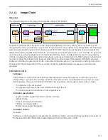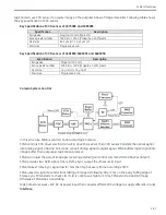
System Overview
2-53
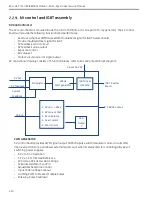
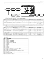
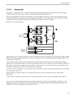
Main
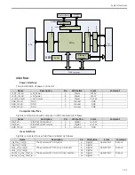
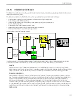
transformer
Rectifier
bridge
DC bus
capacitor
IGBT Board
AC
Monoblock
F
Q1
Q2
Q3
Q4
kV Control
board
Drive power
transformer
Resonant
circuit
L
D
C
R
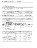
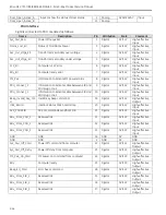
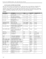
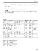
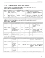
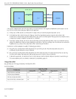
Signals from MCB to KV control board are listed as follows.
Name
Description
Attribution Scale
Comment
SAFETY_EN
Safety line for EXPOSURE_COMMAND
Digital
0/+15V
+15V=enable
0V=disable
EXPOSURE_COMMAND
Exposure command
Digital
0/+15V
+15V=enable
0V=disable
KV_SET_INPUT
KV set value to KV control board
Analog
0-6V
Unit is 20KV/V
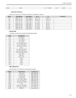
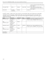
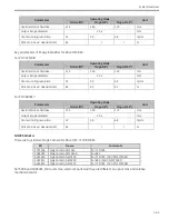
Signals from KV control board to MCB are listed as follows.
Name
Description
Attribution Scale
Comment
KV_LOW_ALM
KV too low alarm, lower than 35KV
Digital
0/+15V
0V=alarm
KV_HIGH_ALM
KV too High alarm, higher than 120KV
Digital
0/+15V
0V=alarm
OVERCURRENT_ALM
Inverter over current alarm
Digital
0/+15V
0V=alarm
IGBT_ERROR_ALM
IGBT error alarm
Digital
0/+15V
0V=alarm
DC_ERROR_ALM
DC Power Bus Error alarm
Digital
0/+15V
0V=alarm
KV_UNBALANCE_ALM
KV unbalance in two bridges of inverter.
Digital
0/+15V
0V=alarm
KV_FEEDBACK_OUTPUT KV sample value from KV control board
Analog
0-6V
Unit 20KV/V
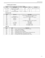
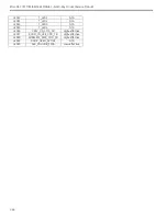
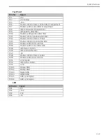
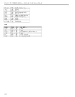
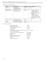
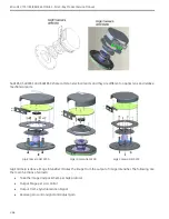
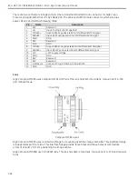
Test Point
Pin
Description
TP1
+15V
TP2
Output A of SG3525
TP3
Output B of SG3525
TP4
The frequence of SG3525
TP5
GND
TP6
GND
TP7
+5V
TP8
-15V
TP9
GND
TP10
The current feedback of inverter output
TP11
The control voltage of KV PI
TP12
The control voltage of KV PI with inverter current
TP13
KV PI output
TP14
Midpoint of KV
TP15
KV feedback output
Summary of Contents for Brivo OEC 715
Page 2: ......
Page 19: ...Chapter1 Introduction and Safety...
Page 41: ...Introduction and Safety 23 46 54 20 18 26...
Page 55: ...Chapter2 System Overview...
Page 137: ...Chapter3 Installation...
Page 212: ...Chapter4 Calibration...
Page 275: ...Brivo OEC 715 785 865 Mobile C Arm X Ray Product Service Manual 4 64...
Page 284: ...Chapter5 Software...
Page 326: ...Software 5 43 2 Click on install to continue 3 Click Next to continue...
Page 335: ...Chapter6 Troubleshooting...
Page 408: ...Chapter7 Replacement...
Page 418: ...Replacement 7 11 166...
Page 488: ...Chapter8 Periodic Maintenance...
Page 502: ...Periodic Maintenance 8 15...
Page 505: ...Chapter9 Technical Reference...
Page 521: ...Technical Reference 9 17 Vertical configuration 1 5m Vertical configuration 1m...
Page 526: ...11 Appendix System Schematics...

