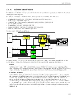
System Overview
2-45
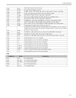
GND
GND
18 GND
0V
GND
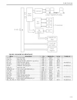
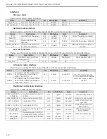
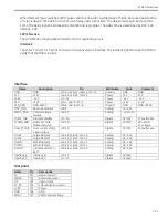
Ethernet Interface
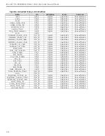
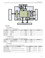
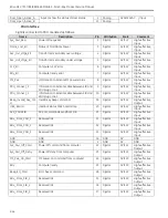
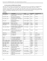
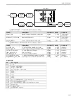
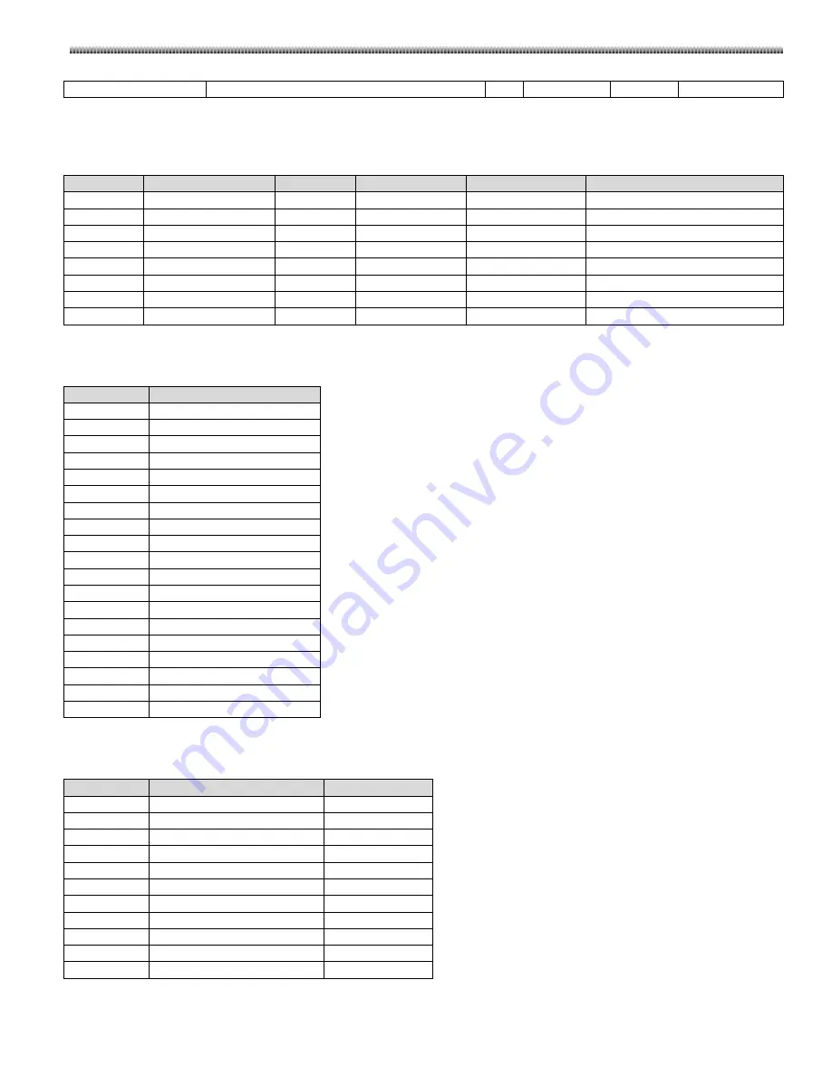
Signals connected to Ethernet Interface are listed as follows.
Name
Description
Attribution
From
To
Comment
CX1+
Ethernet CX1+
Differential
S10 pin 11
S9 pin 11
CX1-
Ethernet CX1-
Differential
S10 pin 10
S9 pin 10
CX2+
Ethernet CX2+
Differential
S10 pin 4
S9 pin 4
CX2-
Ethernet CX2-
Differential
S10 pin 5
S9 pin 5
CX3+
Ethernet CX3+
Differential
S10 pin 3
S9 pin 3
CX3-
Ethernet CX3-
Differential
S10 pin 2
S9 pin 2
CX4+
Ethernet CX4+
Differential
S10 pin 8
S9 pin 8
CX4-
Ethernet CX4-
Differential
S10 pin 9
S9 pin 9
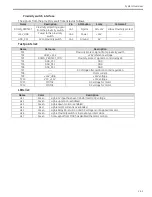
Test Points
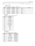
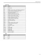
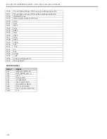
The SIB provides test points for following signals:
Name
Description
TP1
+5V power
TP2
+3.3V power
TP3
+2.5V power
TP4
+1.2V power
TP5
+12V_Cmptr power
TP6
+5V_Cmptr power
TP7
MF_Pwr_On_Cmd
TP8
Rdy
TP9
Sys_Pwr_Off_Cmd
TP10
Sys_Pwr_Off_Deny
TP11
ACK_PDU2SIB_FPGA
TP12
CLK_FPGA
TP13
DEV_OEn
TP14
DEV_CLRn
TP15
GND
TP16
GND
TP17
GND
TP18
GND
TP19
GND
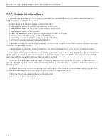
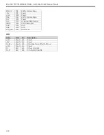
LED Indicators
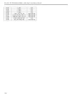
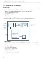
SIB provides LED indicator for following signals:
Name
Description
Comments
LED1
+5V power
High=effective
LED2
+3.3V power
High=effective
LED3
+2.5V power
High=effective
LED4
+1.2V power
High=effective
LED5
+12V_Cmptr power
High=effective
LED6
+5V_Cmptr power
High=effective
LED7
MF_Pwr_On_Cmd
Low=effective
LED8
Rdy
Low=effective
LED9
Sys_Pwr_Off_Cmd
Low=effective
LED10
Sys_Pwr_Off_Deny
Low=effective
LED11
NRESET
Low=effective
Summary of Contents for Brivo OEC 715
Page 2: ......
Page 19: ...Chapter1 Introduction and Safety...
Page 41: ...Introduction and Safety 23 46 54 20 18 26...
Page 55: ...Chapter2 System Overview...
Page 137: ...Chapter3 Installation...
Page 212: ...Chapter4 Calibration...
Page 275: ...Brivo OEC 715 785 865 Mobile C Arm X Ray Product Service Manual 4 64...
Page 284: ...Chapter5 Software...
Page 326: ...Software 5 43 2 Click on install to continue 3 Click Next to continue...
Page 335: ...Chapter6 Troubleshooting...
Page 408: ...Chapter7 Replacement...
Page 418: ...Replacement 7 11 166...
Page 488: ...Chapter8 Periodic Maintenance...
Page 502: ...Periodic Maintenance 8 15...
Page 505: ...Chapter9 Technical Reference...
Page 521: ...Technical Reference 9 17 Vertical configuration 1 5m Vertical configuration 1m...
Page 526: ...11 Appendix System Schematics...

