Brivo OEC 715/785/865 Mobile C-Arm X-Ray Product Service Manual
6-2
WARNING
6.1.
Overview
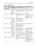
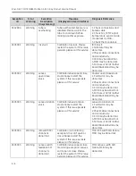
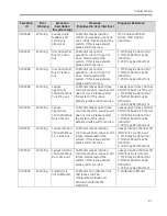
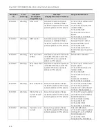
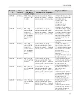
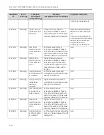
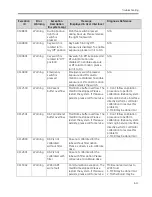
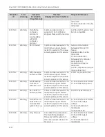
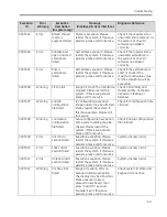
This chapter describes messages that appear on the right workstation monitor during system operation.
Messages may indicate any of the following:
•
Error Messages
•
Warning Messages
•
Information
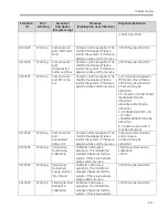
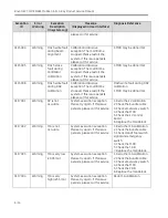
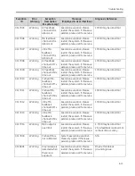
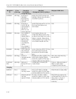
When the error message appears, error code will also be displayed on the kV, mA display field on control
panel, if the Mainframe is connected with Workstation.
6.2.
Error Recovery Steps
Perform the following error recovery procedures if you encounter problems during start-up or operation:
1.
Some messages can be cleared by pressing OK button or taking exposure, but will periodically re-
display while the condition exists.
2.
If an error message occurs, shutdown the system. Wait one minute, and then press the power on key.
If this fails to restore normal operation then proceed with step 3.
3.
Press the power off key, disconnect the power cord, and call for service. Refer to chapter 1 for
communication center telephone numbers. Do not continue using the system.
System may fail at any time. Ignoring error and warning messages may result in
equipment damage and personal injury.
6.3.
Event Messages
6.3.1.
Structure of Message Code
Three subcodes constitute the message:
Subsystem Code
Component Code Exception No.
Message ID
Description
**
**
***
**_**_***
-------
Example:
01
02
001
01 02 001
Tube temperature sensor
feedback SPI line work
abnormal
Summary of Contents for Brivo OEC 715
Page 2: ......
Page 19: ...Chapter1 Introduction and Safety...
Page 41: ...Introduction and Safety 23 46 54 20 18 26...
Page 55: ...Chapter2 System Overview...
Page 137: ...Chapter3 Installation...
Page 212: ...Chapter4 Calibration...
Page 275: ...Brivo OEC 715 785 865 Mobile C Arm X Ray Product Service Manual 4 64...
Page 284: ...Chapter5 Software...
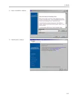
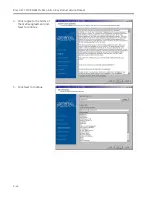
Page 326: ...Software 5 43 2 Click on install to continue 3 Click Next to continue...
Page 335: ...Chapter6 Troubleshooting...
Page 408: ...Chapter7 Replacement...
Page 418: ...Replacement 7 11 166...
Page 488: ...Chapter8 Periodic Maintenance...
Page 502: ...Periodic Maintenance 8 15...
Page 505: ...Chapter9 Technical Reference...
Page 521: ...Technical Reference 9 17 Vertical configuration 1 5m Vertical configuration 1m...
Page 526: ...11 Appendix System Schematics...

