Periodic Maintenance
8-7
WARNING
8.4.5.
Ground Continuity
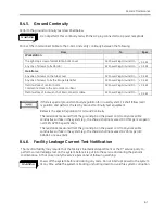
Perform the ground continuity test described below.
Do not perform this continuity test with the AC plug connected to a power receptacle.
Connect the Interconnect Cable to the C-Arm and verify continuity between the following:
From
To
Spec
Workstation
The right-top screw of WorkStation back cover
AC Power Plug Ground Pin
< 0.5
Ω
Any one of screws to fix Monitor
AC Power Plug Ground Pin
< 0.5
Ω
Mainframe
Any one of screws on the tube cover
AC Power Plug Ground Pin
< 0.5
Ω
Any one of screws to fix the Image Intensifier
AC Power Plug Ground Pin
< 0.5
Ω
Metal surface of central C-arm.
Comments: Close to the zero mark of orbital.
AC Power Plug Ground Pin
< 0.5
Ω
Metal surface of lock wrench of interconnector cable
AC Power Plug Ground Pin
< 0.5
Ω
If there is special ground continuity regulation for in used system, FE shall follow local
regulation and perform the test by Ground Continuity test equipment.
Below is the special regulation for Ground Continuity:
The resistance measured from the ground pin on the power cord to any accessible
conductive surface in the system (e.g., the chasis) shall not exceed 0.3 Ohm per European
norm EN 62353, specification.
The resistance measured from the ground pin on the power cord to any accessible
conductive surface in the system (e.g., the chasis) shall not exceed 0.2 ohms per IEC
60601-1 or equivalent.
8.4.6.
Facility Leakage Current Test Notification
The medical facility may require that the facility’s biomedical department or the 3
rd
service party to
perform current leakage test on the system before it is put into the service and during the periodic
maintenance. In that case, notify the service personnel of following warning:
Power off the system before and during any tests. Do not interrupt power to the system
at any time while the system is booting or shutting down to avoid file system corruption.
WARNING
Summary of Contents for Brivo OEC 715
Page 2: ......
Page 19: ...Chapter1 Introduction and Safety...
Page 41: ...Introduction and Safety 23 46 54 20 18 26...
Page 55: ...Chapter2 System Overview...
Page 137: ...Chapter3 Installation...
Page 212: ...Chapter4 Calibration...
Page 275: ...Brivo OEC 715 785 865 Mobile C Arm X Ray Product Service Manual 4 64...
Page 284: ...Chapter5 Software...
Page 326: ...Software 5 43 2 Click on install to continue 3 Click Next to continue...
Page 335: ...Chapter6 Troubleshooting...
Page 408: ...Chapter7 Replacement...
Page 418: ...Replacement 7 11 166...
Page 488: ...Chapter8 Periodic Maintenance...
Page 502: ...Periodic Maintenance 8 15...
Page 505: ...Chapter9 Technical Reference...
Page 521: ...Technical Reference 9 17 Vertical configuration 1 5m Vertical configuration 1m...
Page 526: ...11 Appendix System Schematics...

