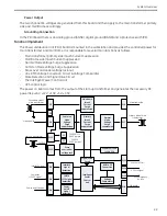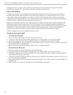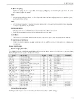
Brivo OEC 715/785/865/865 Mobile C-Arm X-Ray Product Service Manual
2-8
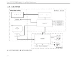
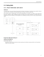
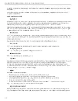
Common Mode
Voltage
Surge
suppression
Primary
Inrush
Current
Surge
suppression
Normal Mode
Voltage
Surge
suppression
Primary
Side
Of main
transformer
Secondary
Side
Of main
transformer
Mainframe
Inrush
Current
Surge
suppression
Mainframe
User
interface
Interlock Signal
CMPTR +12V Signal
Power ON/OFF Signal
WKS ON/OFF Signal
CPLD
System
Interface
Board
Drive circuit
Drive circuit
Power on
board
Mains power
Power Input
AC main power input:
This is a AC main input with bias
±
15%. It supports multiple rated voltages configuration with
100V/110V/120V/200V/220V/230V/240VAC (RMS).
Secondary side of main transformer:
Another input comes from the secondary side output of main transformer. The rated voltage is 220V (RMS)
and 28V (RMS) for up-down board and mainframe.
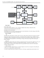
Power On Board
+24V
When the main input power is ok with no gross over and under voltage condition, the relay K6 is activated
and the AC voltage of secondary side of start_up transformer (BT2) is applied at the D7 (2W06), then the
rectified DC voltage connected to the input pins of U4 (LM317T) and the output voltage is about +24VDC by
the configuration of R10 and R8. The +24V voltage is mainly to drive relays and get other necessary DC
power on board.
VCC_+12V
To make sure the WKS on/off control relay (K7) work properly in AC main power lost condition, the VCC_+12V
DC power use dual power method by the simple parallel of 12V and +12V. 12V is
connected the +12V power from computer and +12V is generated from the conversion of low dropout
regulator LM2940CT-12(D26).
+10V, +5V, +3.3V
To get more accurate voltage reference in voltage comparison circuit, the +10V power is achieved by the
+10V precision voltage reference REF01SC3 (D9).
+5V power is generated by the LM2940CS-5.0 (D8) and +3.3V power is generated by the LM1084-3.3.(U5)
Summary of Contents for Brivo OEC 715
Page 2: ......
Page 19: ...Chapter1 Introduction and Safety...
Page 41: ...Introduction and Safety 23 46 54 20 18 26...
Page 55: ...Chapter2 System Overview...
Page 137: ...Chapter3 Installation...
Page 212: ...Chapter4 Calibration...
Page 275: ...Brivo OEC 715 785 865 Mobile C Arm X Ray Product Service Manual 4 64...
Page 284: ...Chapter5 Software...
Page 326: ...Software 5 43 2 Click on install to continue 3 Click Next to continue...
Page 335: ...Chapter6 Troubleshooting...
Page 408: ...Chapter7 Replacement...
Page 418: ...Replacement 7 11 166...
Page 488: ...Chapter8 Periodic Maintenance...
Page 502: ...Periodic Maintenance 8 15...
Page 505: ...Chapter9 Technical Reference...
Page 521: ...Technical Reference 9 17 Vertical configuration 1 5m Vertical configuration 1m...
Page 526: ...11 Appendix System Schematics...

