Calibration
4-21
4.4.
mAs Measurement and Calibration
4.4.1.
mAs Measurment and Accuracy Check
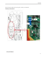
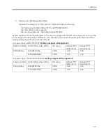
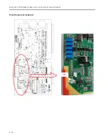
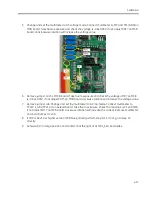
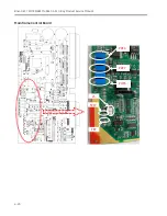
Remove J46 jumper on extend board. Connect the probes of ampere meter to TP222 (+) and TP210 (-) on
extend board. Connect the mAs meter to ampere meter in serial.
Take exposure by the parameters below. The error of mAs should be within
±
10%.
kV, mAs
Minimum (mAs)
Maximum (mAs)
40KV, 40mAs
36
44
60KV, 20mAs
18
22
80KV, 10mAs
9
11
110kV, 1mAs
0.9
1.1
4.4.2.
mAs Calibration
1.
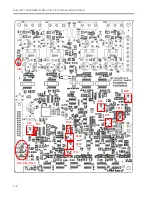
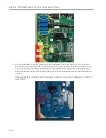
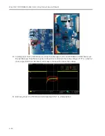
Take exposure at 80kVp, 20mAs. Adjust POT2 on MCB board until the measured mAs value is
20.0mAs
±
1mAs.
2.
Check mAs accuracy according to section 4.4.1.
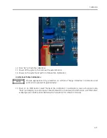
After the calibration, connect the jumper to J46 on extend board.
3.
After the calibration process completion, remove the extend board and recover the system.
4.5.
X-Ray Generator Warm-up
This procedure is used to improve the life of the X-Ray generator. It is only required if the Generator is not
powered for more than 3 months.
1.
Power on the system
2.
Close the collimator IRIS and place a lead shield in the X-Ray beam to protect the Image
Intensifier and CCD camera.
3.
Select the Manual Fluoroscopy mode. Set the kVp value to 60 kVp@1mA. Take an exposure for 3
minutes.
4.
Wait for 5 minutes after exposure.
5.
Set the kVp value to 80kVp@1mA and take an exposure for 3 minutes.
6.
Wait for 5 minutes.
7.
Power off the system.
Summary of Contents for Brivo OEC 715
Page 2: ......
Page 19: ...Chapter1 Introduction and Safety...
Page 41: ...Introduction and Safety 23 46 54 20 18 26...
Page 55: ...Chapter2 System Overview...
Page 137: ...Chapter3 Installation...
Page 212: ...Chapter4 Calibration...
Page 275: ...Brivo OEC 715 785 865 Mobile C Arm X Ray Product Service Manual 4 64...
Page 284: ...Chapter5 Software...
Page 326: ...Software 5 43 2 Click on install to continue 3 Click Next to continue...
Page 335: ...Chapter6 Troubleshooting...
Page 408: ...Chapter7 Replacement...
Page 418: ...Replacement 7 11 166...
Page 488: ...Chapter8 Periodic Maintenance...
Page 502: ...Periodic Maintenance 8 15...
Page 505: ...Chapter9 Technical Reference...
Page 521: ...Technical Reference 9 17 Vertical configuration 1 5m Vertical configuration 1m...
Page 526: ...11 Appendix System Schematics...

