Introduction and Safety
25
1.2.13.
Symbols
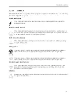
Be familiar with the following symbols that may appear on equipment and schematics so you can safely
maintain and operate the system:
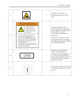
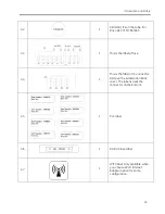
Dangerous Voltage
This symbol identifies areas where hazardous voltages may be present. Use appropriate
safety precautions.
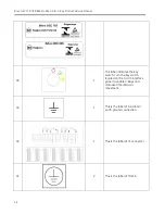
Protective Earth Ground
This symbol identifies the system’s main protective earth ground terminal, which connects to
the facility earth ground through the grounding prong on the AC power plug. This connection
must be in place at all times for safe system operation.
Earth Ground Connection
This symbol identifies an earth ground connection that is necessary to maintain grounding
throughout the system.
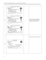
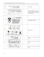
X-Ray Source
This X-Ray Source symbol is used to identify controls that will produce ionizing X-radiation
when activated. Always use appropriate safety precautions when generating X-Rays.
This X-Ray Source symbol is used to identify controls that will produce ionizing X-radiation
when activated. Always use appropriate safety precautions when generating X-Rays.
Potential Equalization Terminal
This symbol identifies system terminals which, when connected together, are at the same
potential (not necessarily earth ground). Green/yellow wires normally connect potential
equalization terminals together.
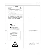
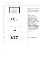
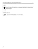
Attention
Attention, see accompanying documentation for information. You can refer to this manual for
the operation instructions.
Summary of Contents for Brivo OEC 715
Page 2: ......
Page 19: ...Chapter1 Introduction and Safety...
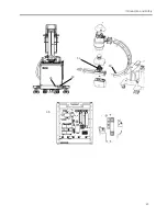
Page 41: ...Introduction and Safety 23 46 54 20 18 26...
Page 55: ...Chapter2 System Overview...
Page 137: ...Chapter3 Installation...
Page 212: ...Chapter4 Calibration...
Page 275: ...Brivo OEC 715 785 865 Mobile C Arm X Ray Product Service Manual 4 64...
Page 284: ...Chapter5 Software...
Page 326: ...Software 5 43 2 Click on install to continue 3 Click Next to continue...
Page 335: ...Chapter6 Troubleshooting...
Page 408: ...Chapter7 Replacement...
Page 418: ...Replacement 7 11 166...
Page 488: ...Chapter8 Periodic Maintenance...
Page 502: ...Periodic Maintenance 8 15...
Page 505: ...Chapter9 Technical Reference...
Page 521: ...Technical Reference 9 17 Vertical configuration 1 5m Vertical configuration 1m...
Page 526: ...11 Appendix System Schematics...

