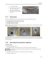
Installation
3-59
WARNING
CAUTION
8.
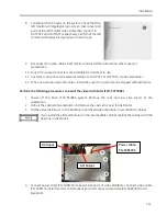
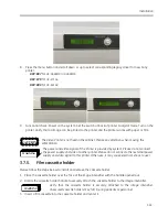
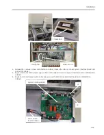
Press the menu button and scroll down or up to select corresponding legacy driver for new Sony
printer.
DRV: 897
for
UP-D898MD/ UP-X898MD
DRV: 970
for
UP-971AD
DRV: 990
for
UP-991AD
9.
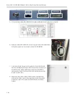
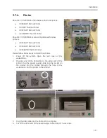
Functional check: Power on the system. Set the switch at back of printer to digital mode. Turn on the
printer. Verify that an image can be printed to the printer and the printer works with paper or film.
The Video Printer is not fixed in the cabinet. Please pay attention when moving the
WorkStation.
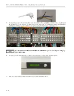
The power and video signal of the Printer is provided by system. Please do not connect
the power supply and video to other printer. Please do not connect other external power
supply and video signal to this printer. Otherwise, it may cause electrical shock to user.
3.7.5.
Film cassette holder
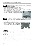
Please follow the steps below to install and remove the cassette holder:
1.
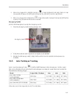
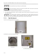
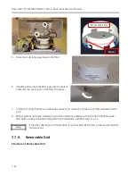
Place the cassette holder over the face of the image intensifier with the handle opened out.
2.
Rotate the cassette holder handle to securely attach the cassette holder to the image intensifier.
Verify that the cassette holder is securely attached to the image intensifier.
Unsecured cassette holders may fall, injuring patients or personnel.
3.
Insert a film cassette into the cassette holder and center it.
WARNING
Summary of Contents for Brivo OEC 715
Page 2: ......
Page 19: ...Chapter1 Introduction and Safety...
Page 41: ...Introduction and Safety 23 46 54 20 18 26...
Page 55: ...Chapter2 System Overview...
Page 137: ...Chapter3 Installation...
Page 212: ...Chapter4 Calibration...
Page 275: ...Brivo OEC 715 785 865 Mobile C Arm X Ray Product Service Manual 4 64...
Page 284: ...Chapter5 Software...
Page 326: ...Software 5 43 2 Click on install to continue 3 Click Next to continue...
Page 335: ...Chapter6 Troubleshooting...
Page 408: ...Chapter7 Replacement...
Page 418: ...Replacement 7 11 166...
Page 488: ...Chapter8 Periodic Maintenance...
Page 502: ...Periodic Maintenance 8 15...
Page 505: ...Chapter9 Technical Reference...
Page 521: ...Technical Reference 9 17 Vertical configuration 1 5m Vertical configuration 1m...
Page 526: ...11 Appendix System Schematics...

