System Overview
2-29
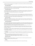
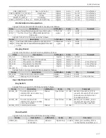
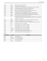
switch1
connected means
EMERGENCY_SWT has been
pressed
REF_
EMERGENCY_SWT1
The other
termination of
Emergency
switch1
Passive
-
J1-B11 -
EMERGENCY_SWT2 One termination of
Emergency
switch2
Passive
Open/Close J1-C25 EMERGENCY_SWT2 &
REF_EMERGENCY_SWT2 is not
connected means
EMERGENCY_SWT2 has been
pressed
REF_
EMERGENCY_SWT2
The other
termination of
Emergency
switch2
Passive
-
J1-A26 -
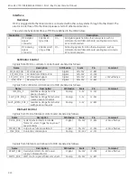
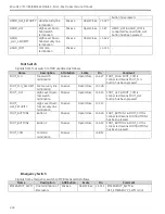
Removable Filter
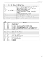
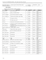
Signals from removable filter to MCB are listed as follows.
Name
Description
Attribution
Scale
Pin
Comment
PROTECT_A
Removable filter A
sensor signal
Digital
0V/+15V
J1-B31 +15V= Filter removed
PROTECT_B
Removable filter B
sensor signal
Digital
0V/+15V
J1-B30 +15V= Filter removed
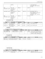
Indicator
Signals from MCB to indicator are listed as follows.
Name
Description
Attribution
Scale
Pin
Comment
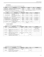
XRAY_INDICATOR_A
Anode of indicator
Passive
-
J1-B8
The indicator will be lighted when a
certain current about 12mA flows
from XRAY_INDICATOR_A through
indicator to XRAY_INDICATOR_B.
XRAY_INDICATOR_B
Cathode of indicator
Passive
-
J1-A8
Program Port
Program port signals are listed as follows.
Name
Description
Attribution
Scale
Pin
Comment
SERIAL_TXD
Transmit signal of serial port
Digital
-7V-+7V
J1-A31 -
SERIAL_RXD
Receive signal of serial port
Digital
-7V-+7V
J1-C22 -
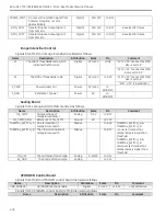
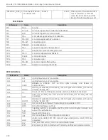
Interlock Loop
Interlock loop signals are listed as follows.
Name
Description
Attribution
Scale
Pin
Comment
INTERLOCK_LOOP_A One termination of
interlock loop
Passive
-
J2-B16 INTERLOCK_LOOP_A &
INTERLOCK_LOPP_B is connected in
Summary of Contents for Brivo OEC 715
Page 2: ......
Page 19: ...Chapter1 Introduction and Safety...
Page 41: ...Introduction and Safety 23 46 54 20 18 26...
Page 55: ...Chapter2 System Overview...
Page 137: ...Chapter3 Installation...
Page 212: ...Chapter4 Calibration...
Page 275: ...Brivo OEC 715 785 865 Mobile C Arm X Ray Product Service Manual 4 64...
Page 284: ...Chapter5 Software...
Page 326: ...Software 5 43 2 Click on install to continue 3 Click Next to continue...
Page 335: ...Chapter6 Troubleshooting...
Page 408: ...Chapter7 Replacement...
Page 418: ...Replacement 7 11 166...
Page 488: ...Chapter8 Periodic Maintenance...
Page 502: ...Periodic Maintenance 8 15...
Page 505: ...Chapter9 Technical Reference...
Page 521: ...Technical Reference 9 17 Vertical configuration 1 5m Vertical configuration 1m...
Page 526: ...11 Appendix System Schematics...

