Calibration
4-43
4.6.5.
I.I. Field Size Check and Calibration
I.I. Field Size Check
1.
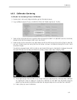
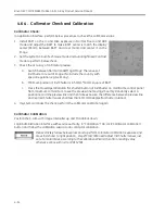
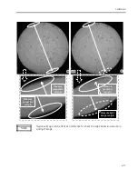
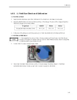
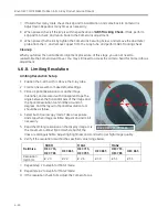
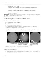
Select relative field size, open the collimator to the maximum, and take an exposure.
2.
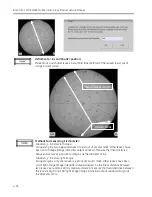
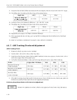
Read the BAFT/UBAT tick mark on the boundary of the image. The size of the image should be
within the range of the values below.
Mag Mode
NORM
MAG1
MAG2
Displayed Image Diameter (mm)
210
±
10
155
±
8
115
±
8
3.
If the size of the image is out of requirement, I.I. Field Size Calibration shall be performed.
I.I. Field Size Calibration
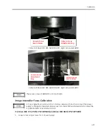
I. I. Size adjustment is done in the I.I. factory. Adjust with much care only if the Power
Supply is changed or repaired. Always use non-metal flathead screwdriver to adjust the
I.I. potentiometer to avoid short circuit.
1.
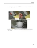
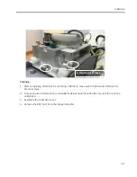
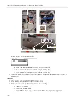
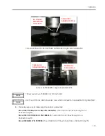
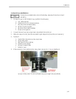
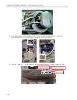
Loosen the 2 I.I. power supply fixed screws.
2.
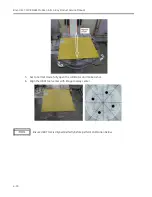
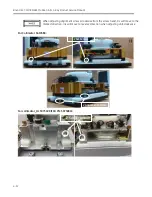
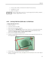
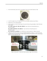
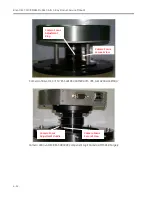
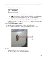
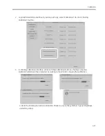
Disconnect relative cables to take out the I.I. Power Supply. Carefully adjust I. I. Field Size
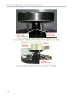
potentiometer. Below are two ways to fix I.I. power supply in calibration:
Summary of Contents for Brivo OEC 715
Page 2: ......
Page 19: ...Chapter1 Introduction and Safety...
Page 41: ...Introduction and Safety 23 46 54 20 18 26...
Page 55: ...Chapter2 System Overview...
Page 137: ...Chapter3 Installation...
Page 212: ...Chapter4 Calibration...
Page 275: ...Brivo OEC 715 785 865 Mobile C Arm X Ray Product Service Manual 4 64...
Page 284: ...Chapter5 Software...
Page 326: ...Software 5 43 2 Click on install to continue 3 Click Next to continue...
Page 335: ...Chapter6 Troubleshooting...
Page 408: ...Chapter7 Replacement...
Page 418: ...Replacement 7 11 166...
Page 488: ...Chapter8 Periodic Maintenance...
Page 502: ...Periodic Maintenance 8 15...
Page 505: ...Chapter9 Technical Reference...
Page 521: ...Technical Reference 9 17 Vertical configuration 1 5m Vertical configuration 1m...
Page 526: ...11 Appendix System Schematics...

