Installation
3-71
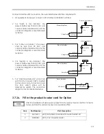
For Room Interface (RIF) connection, the rules listed below shall be complied with:
1.
All equipment and power connect to RIF shall be UL/IEC60601 certified.
2.
For “Room in Use Indicator”, the
power shall be less than DC 36V, and
current shall be limited within 2A. The
connection diagram is recommended
as below.
3.
For “X-Ray on Indicator”, the power
shall be less than DC 36V, and
current shall be limited within 2A. The
connection diagram is recommended
as below.
4.
For “Injector in Use Indicator”, the
power shall be less than DC 36V, and
current shall be limited within 2A. The
connection diagram is recommended
as below.
5.
For “Door Open Detector”, an AC 24V
with minimum power 24W is needed
to drive an AC relay in internal circuit,
the door switch status will be
detected by system. The connection
diagram is recommended as below.
3.7.14.
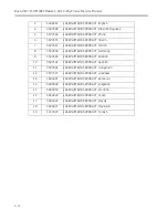
Fill in the product locator card for Option
After the installation of option parts, please fill in the product locator card for PLC parts
below and mail the cards to local service operation office.
Item
Part Number
Part Description
1
5075816
ASM, MONOBLOCK COVER WITH LASER AIMER KIT
2
5085005
ASM, 9 Inch Cassette Holder
Room Interface
Relay Switch
Power<36V
Room In Use Indicator
R
I<2A
RIF Pin14
RIF Pin15
Room Interface
Relay Switch
Power<36V
Xray On Indicator
R
I<2A
RIF Pin9
RIF Pin10
Room Interface
Relay Switch
Power<36V
R
I<2A
RIF Pin4
RIF Pin5
Injector
Room Interface
RIF Pin1
RIF Pin11
AC24V
AC Relay Core
Door Switch
Summary of Contents for Brivo OEC 715
Page 2: ......
Page 19: ...Chapter1 Introduction and Safety...
Page 41: ...Introduction and Safety 23 46 54 20 18 26...
Page 55: ...Chapter2 System Overview...
Page 137: ...Chapter3 Installation...
Page 212: ...Chapter4 Calibration...
Page 275: ...Brivo OEC 715 785 865 Mobile C Arm X Ray Product Service Manual 4 64...
Page 284: ...Chapter5 Software...
Page 326: ...Software 5 43 2 Click on install to continue 3 Click Next to continue...
Page 335: ...Chapter6 Troubleshooting...
Page 408: ...Chapter7 Replacement...
Page 418: ...Replacement 7 11 166...
Page 488: ...Chapter8 Periodic Maintenance...
Page 502: ...Periodic Maintenance 8 15...
Page 505: ...Chapter9 Technical Reference...
Page 521: ...Technical Reference 9 17 Vertical configuration 1 5m Vertical configuration 1m...
Page 526: ...11 Appendix System Schematics...

