Brivo OEC 715/785/865/865 Mobile C-Arm X-Ray Product Service Manual
2-26
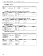
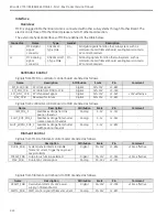
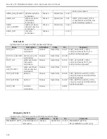
FRAME_SYNC Frame synchronization signal from
Camera. Frequency is 25Hz
approximately
Digital
0V/+15V
J1-B24
-
GPIO_OUT2
General Purpose Output signal 2
from Camera
Digital
0V/+15V
J1-B21
Reversed for future
GPIO_OUT3
General Purpose Output signal 3
from Camera
Digital
0V/+15V
J1-B20
Reversed for future
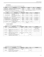
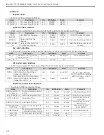
Image Intensifier Control
Signals from MCB to II (Image Intensifier) are listed as follows.
Name
Description
Attribution
Scale
Pin
Comment
F1
The LSB of three fields code, which
indicates the MAG size.
Digital
0V/+24V
J1-A9
“F2F1”=”00” means that MAG
size is set to 9’’
“F2F1”=”01” means that MAG
size is set to 4.5’’
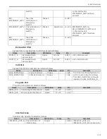
F2
The MSB of three fields code
Digital
0V/+24V
J1-A10
“F2F1”=”10” means that MAG
size is set to 6’’
“F2F1”=”11” is invalidation
II_PWR
Power supply of II
Power
0V/+24V
J1-
A2/B2/C2
-
II_GND
Reference of power
Power
0V
J1-
A3/B3/C3
-
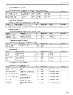
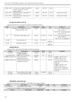
Sealing Board
Signals from sealing board to MCB are listed as follows.
Name
Description
Attribution
Scale
Pin
Comment
OIL_TEMP
Output voltage of
temperature sensor
Analog
0-5V
J2-B13
-
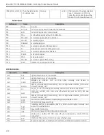
OIL_TEMP_GND
Reference of OIL_TEMP
Ground
0V
J2-C13
-
THERMAL_SWITCH_A One termination of
temperature switch
Passive
-
J1-B26
THERMAL_SWITCH_A &
THERMAL_SWITCH_B
connected means that
temperature is lower than
threshold.
THERMAL_SWITCH_A &
THERMAL_SWITCH_B
disconnected means that
temperature is higher than
threshold.
THERMAL_SWITCH_B The other termination of
temperature switch
Passive
-
J1-B27
MA_CAT
The cathode of mA sample
Analog
0-20mA
J2-A14
-
KV_GND
The anode of mA sample
Analog
-
J2-C14
-
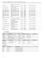
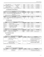
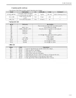
UP/DOWN Control Board
Signals from MCB to UP/DOWN control board are listed as follows.
Name
Description
Attribution
Scale
Pin
Comment
UDB_ENABLE
UP/DOWN function enable
Digital
0-+15V
J1-C14
+15V=effective
Signals from UP/DOWN control board to MCB are listed as follows.
Name
Description
Attribution
Scale
Pin
Comment
Summary of Contents for Brivo OEC 715
Page 2: ......
Page 19: ...Chapter1 Introduction and Safety...
Page 41: ...Introduction and Safety 23 46 54 20 18 26...
Page 55: ...Chapter2 System Overview...
Page 137: ...Chapter3 Installation...
Page 212: ...Chapter4 Calibration...
Page 275: ...Brivo OEC 715 785 865 Mobile C Arm X Ray Product Service Manual 4 64...
Page 284: ...Chapter5 Software...
Page 326: ...Software 5 43 2 Click on install to continue 3 Click Next to continue...
Page 335: ...Chapter6 Troubleshooting...
Page 408: ...Chapter7 Replacement...
Page 418: ...Replacement 7 11 166...
Page 488: ...Chapter8 Periodic Maintenance...
Page 502: ...Periodic Maintenance 8 15...
Page 505: ...Chapter9 Technical Reference...
Page 521: ...Technical Reference 9 17 Vertical configuration 1 5m Vertical configuration 1m...
Page 526: ...11 Appendix System Schematics...

