Technical Reference
9-19
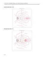
Horizontal Plane&
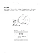
Vertical Plane Test
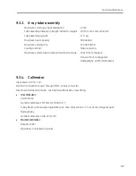
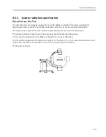
This test is performed at in fluoroscopic mode in 70kV, 3mA, without shielding.
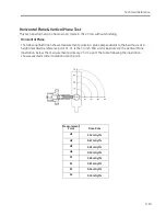
Horizontal Plane
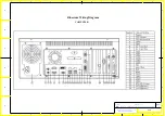
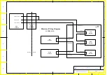
The following illustration shows measurement points in a plane perpendicular to the beam axis at a
height indicated by reference point C1. C1 is the 30-inch SSD, and is illustrated in the Vertical Plane
illustration, below. The measurement points are 25 cm apart. The table following the illustration
shows expected scatter radiation at each point.
Measurement
Point
Dose Rate
H1
3.32 mGy/hr
H2
0.67 mGy/hr
H3
0.28 mGy/hr
H4
0.19 mGy/hr
S1
3.60 mGy/hr
S2
0.81 mGy/hr
S3
0.36 mGy/hr
S4
0.19 mGy/hr
Summary of Contents for Brivo OEC 715
Page 2: ......
Page 19: ...Chapter1 Introduction and Safety...
Page 41: ...Introduction and Safety 23 46 54 20 18 26...
Page 55: ...Chapter2 System Overview...
Page 137: ...Chapter3 Installation...
Page 212: ...Chapter4 Calibration...
Page 275: ...Brivo OEC 715 785 865 Mobile C Arm X Ray Product Service Manual 4 64...
Page 284: ...Chapter5 Software...
Page 326: ...Software 5 43 2 Click on install to continue 3 Click Next to continue...
Page 335: ...Chapter6 Troubleshooting...
Page 408: ...Chapter7 Replacement...
Page 418: ...Replacement 7 11 166...
Page 488: ...Chapter8 Periodic Maintenance...
Page 502: ...Periodic Maintenance 8 15...
Page 505: ...Chapter9 Technical Reference...
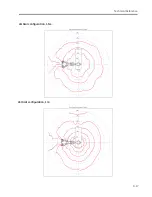
Page 521: ...Technical Reference 9 17 Vertical configuration 1 5m Vertical configuration 1m...
Page 526: ...11 Appendix System Schematics...

