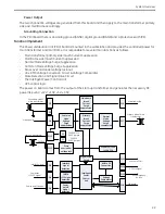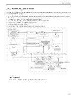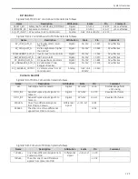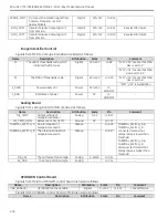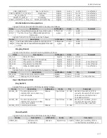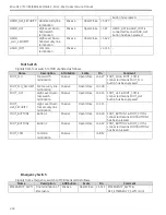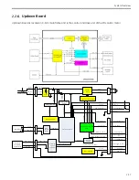
System Overview
2-23
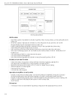
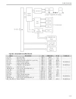
signals are output to KV control board and filament control board through DAC and operational amplifier
circuit or PI circuit sequentially.
Manual kV Setting
Control panel samples the manual kV setting value, and transports it to MCU by SPI bus. MCU looks up the
responding data and sets DAC circuit. Operational amplifier circuit amplifies kV control signal from DAC, and
outputs signal KV_SET_INPUT to kV control board finally.
Manual mA Setting
Control panel samples the manual mA setting value, and transports it to MCU by SPI bus. MCU looks up the
responding data and sends out signals to DAC circuit. The mA control analog signals, KVC and MAC, are
output to filament control board through DAC and PI circuit sequentially.
mAs Control
The setting value of mA is 20mA (or 10mA) in mAS mode. mA sample signal is transformed to pulse by VFC
circuit. The pulse is used as clock signal of down counter in peripheral controller. When mAS mode is set, the
mAS time is set in down counter as the initial value. While exposure starts, down counter works at the same
time. When the value of down counter reduces to 0, exposure stops.
High Level Fluoro
Logically, there is a table that consists of 4 columns: input kV value, input mA value, output kV value and
output mA value. MCU looks up the table by input kV and mA value, and gets output kV and mA value as kV
and mA setting respectively, then outputs those setting.
Auto mA Calibration
Because valid exposure period in each frame is smaller than 40 ms, response time from MAC signal set out
to mA stable should be within a certain time. Meanwhile, the response time is related with the parameters of
tube. The key parameter is the current of tube before exposure. If it is very near the current in exposure
followed, the response time will be short enough to meet the requirement.
Therefore, the rational is that a preheat table is setup to provide the mA_preheat signal in section 6.3.4
Figure 5, which give out a proper current of tube before exposure, and PI control will control mA stable in
several ms’ in exposure.
Unfortunately, the variation exists among the parameters of tubes. Although the variation is small, unique
preheat table should be setup for each tube. In order to get this unique preheat table, auto mA calibration
process shall be as follows.
- The variation is so small that a draft preheat table is generated from mass experiment, which is usable
for calibration
- MCU sends out mA_preheat signal according to the draft preheat table instead of MAC signal to filament
board
- Sample mA feedback (mA_sample signal in section 6.3.4 Figure 5) with ADC unit of MCU
- Then the relationship between MAC and mA of the tube is gotten
- Interpolation to get a unique preheat table of the tube, in which mA value is normalized.
Exposure Control
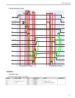
Peripheral controller controls the exposure command and camera LIH (last image hold) as well as other
peripheral control signals. Refer to PDL document.
Debug
JTAG of Peripheral controller and proprietary COM port of MCU has reserved for debug.
Summary of Contents for Brivo OEC 715
Page 2: ......
Page 19: ...Chapter1 Introduction and Safety...
Page 41: ...Introduction and Safety 23 46 54 20 18 26...
Page 55: ...Chapter2 System Overview...
Page 137: ...Chapter3 Installation...
Page 212: ...Chapter4 Calibration...
Page 275: ...Brivo OEC 715 785 865 Mobile C Arm X Ray Product Service Manual 4 64...
Page 284: ...Chapter5 Software...
Page 326: ...Software 5 43 2 Click on install to continue 3 Click Next to continue...
Page 335: ...Chapter6 Troubleshooting...
Page 408: ...Chapter7 Replacement...
Page 418: ...Replacement 7 11 166...
Page 488: ...Chapter8 Periodic Maintenance...
Page 502: ...Periodic Maintenance 8 15...
Page 505: ...Chapter9 Technical Reference...
Page 521: ...Technical Reference 9 17 Vertical configuration 1 5m Vertical configuration 1m...
Page 526: ...11 Appendix System Schematics...

