Calibration
4-25
e.
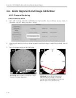
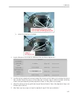
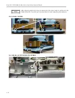
Loosen 3 camera secure screws.
2.
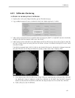
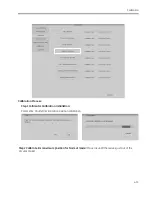
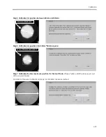
Log in software service mode, in calibration TAB, click “Beam alignment…”
3.
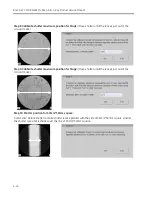
Use the 4 Camera alignment screws to adjust the camera center. Make sure to unscrew one screw
first, and then fasten the screw on the other side to center camera. Perform camera centering
check and repeat adjusting camera alignment screws as many times as necessary.
4.
When the camera centering verification meets the specification, fasten the alignment screws and
camera secure screws.
5.
After fasten secure screws, recheck the alignment result. If fail, redo calibration.
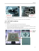
Camera
Securing Screw
Camera Alignment Screws (there
are 4 screws with 90
degrees apart)
Summary of Contents for Brivo OEC 715
Page 2: ......
Page 19: ...Chapter1 Introduction and Safety...
Page 41: ...Introduction and Safety 23 46 54 20 18 26...
Page 55: ...Chapter2 System Overview...
Page 137: ...Chapter3 Installation...
Page 212: ...Chapter4 Calibration...
Page 275: ...Brivo OEC 715 785 865 Mobile C Arm X Ray Product Service Manual 4 64...
Page 284: ...Chapter5 Software...
Page 326: ...Software 5 43 2 Click on install to continue 3 Click Next to continue...
Page 335: ...Chapter6 Troubleshooting...
Page 408: ...Chapter7 Replacement...
Page 418: ...Replacement 7 11 166...
Page 488: ...Chapter8 Periodic Maintenance...
Page 502: ...Periodic Maintenance 8 15...
Page 505: ...Chapter9 Technical Reference...
Page 521: ...Technical Reference 9 17 Vertical configuration 1 5m Vertical configuration 1m...
Page 526: ...11 Appendix System Schematics...

