Brivo OEC 715/785/865 Mobile C-Arm X-Ray Product Service Manual
4-2
4.1.
Overview
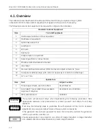
The Calibration described herein should be performed each time you replace a major system
component. Perform these tests in sequence that appears in this section if necessary.
The following tools and test equipment are required to complete the calibration.
Standard Tool and Equipment
Item
Tool and Equipment
1
Oscilloscope Tektronix 2236 or equivalent
2
Multimeter or equivalent
3
Spatial Resolution Tool
4
Lead Apron
5
kV meter
6
Dosimeter
7
Ampere meter or equivalent
8
Ruler longer than 12 inches (30cm)
9
Erasable marker (whiteboard marker)
10
mAs meter
11
Precision flat head screwdriver (
∅
3mm or less) to adjust camera iris, focus
12
Transparent adhesive tape, with cutter (or need scissor or knife to cut the tape)
13
10’’
×
12’’ Film
Special Tool
Item
Tool
GE part number
1
Three copper sheets, each 1mm thick
00-877682-01
2
9-inch BAFT Tool or UBAT (Universal Beam
Alignment Template)
00-878105-02 or 5307604
3
PWA, extend board
5085609
The system will produce X-Rays when implementing the following procedures. Take
appropriate measures and precautions to protect yourself and others from X-Ray
exposure.
Must obey the following steps to guarantee the safe operation of the C-Arm. Improper
adjustment may cause premature failure of major system components.
If the generator has not been powered for more than 3 months, perform the generator
warm-up procedure in section 4.5.
Provide appropriate X-ray protection on surface of Image Intensifier in Image Intensifier
non-ralated calibration and verification to protect Image Intensifier.
WARNING
CAUTION
Summary of Contents for Brivo OEC 715
Page 2: ......
Page 19: ...Chapter1 Introduction and Safety...
Page 41: ...Introduction and Safety 23 46 54 20 18 26...
Page 55: ...Chapter2 System Overview...
Page 137: ...Chapter3 Installation...
Page 212: ...Chapter4 Calibration...
Page 275: ...Brivo OEC 715 785 865 Mobile C Arm X Ray Product Service Manual 4 64...
Page 284: ...Chapter5 Software...
Page 326: ...Software 5 43 2 Click on install to continue 3 Click Next to continue...
Page 335: ...Chapter6 Troubleshooting...
Page 408: ...Chapter7 Replacement...
Page 418: ...Replacement 7 11 166...
Page 488: ...Chapter8 Periodic Maintenance...
Page 502: ...Periodic Maintenance 8 15...
Page 505: ...Chapter9 Technical Reference...
Page 521: ...Technical Reference 9 17 Vertical configuration 1 5m Vertical configuration 1m...
Page 526: ...11 Appendix System Schematics...

