System Overview
2-75
Computer and Peripheral
Computer
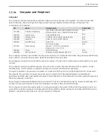
The computer mounted inside the workstation takes over most process of the system. It communicates with
external devices, receives image from GigE camera, process, display and save image. Following is the
configuration of computer.
PN
Name
Configuration
Comments
5075506
Mainboard Assembly
CPU: CORE 3.06G 4M 1156P 2CORE I3-540(G)
Ethernet ports: Two on board Ethernet ports
N/A
5085507
Display Card
1024MB DDR3 PCIE
N/A
5085508
Memory Bank
2G DDR3-1333 240PIN 256X8 HYX(G)
N/A
5085509
Hard Disk
500G 3.5" SATA 7KRPM 16M(G)
N/A
5085511
DVD RW Drive
SATA DVD
Option
5075512
Power Supply
ATX Power Supply:
Input AC : 100~240 50Hz /60Hz
Output: +5V, +/-12V, 3.3V
N/A
5085514
Mouse
PS2/USB Mouse
N/A
5085900
WiFi Connector
Wireless Internet Adaptor 802.11N
Option
The computer contains one 2G DDR3 memory bank and one 3.5” 500G SATA hard disk. The partitioned SATA hard
drive contains Linux operation system, application software and user data.
The computer contains DVI-D and HDMI output for monitor. The DVI-D is for left monitor and the HDMI is for right
monitor.
The computer contains two Ethernet ports. One is for CCD camera, the other Ethernet port is used to connect
DICOM printer. A WiFi collector is optional and used to connect DICOM printer wirelessly.
The system operator can use wire or wireless to connect a DICOM server. Once the Workstation is connected to
the network, the operator can query the local server to determine if the desired images are available for
download, and then download selected images to the Workstation. The Workstation can also upload images over
the same network connection.
Power Supply combined with Battery Pack provides UPS function. If Workstation lost AC power accidentally, UPS
function can provide at least 2 minutes to shutdown computer safely and automatically.
The computer contains three serial ports to communicate with other parts. COM1 is RS232 serial port and is not
used, COM2 is RS232 serial port and talks with SIB board, COM3 is RS422 serial port and talks with MCB board. In
addition, computer will p12V and +5V power to SIB board.
Summary of Contents for Brivo OEC 715
Page 2: ......
Page 19: ...Chapter1 Introduction and Safety...
Page 41: ...Introduction and Safety 23 46 54 20 18 26...
Page 55: ...Chapter2 System Overview...
Page 137: ...Chapter3 Installation...
Page 212: ...Chapter4 Calibration...
Page 275: ...Brivo OEC 715 785 865 Mobile C Arm X Ray Product Service Manual 4 64...
Page 284: ...Chapter5 Software...
Page 326: ...Software 5 43 2 Click on install to continue 3 Click Next to continue...
Page 335: ...Chapter6 Troubleshooting...
Page 408: ...Chapter7 Replacement...
Page 418: ...Replacement 7 11 166...
Page 488: ...Chapter8 Periodic Maintenance...
Page 502: ...Periodic Maintenance 8 15...
Page 505: ...Chapter9 Technical Reference...
Page 521: ...Technical Reference 9 17 Vertical configuration 1 5m Vertical configuration 1m...
Page 526: ...11 Appendix System Schematics...

