System Overview
2-59
Monoblock
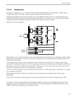
Monoblock can generate X-ray. It mainly consists of high voltage generator and tube insert. All high voltage
components are put into oil box, which can enhance the insulation performance.
Monoblock generates 110kV inside the oil tank. The input voltage changes from 0V to 240V peak value. High
voltage is got from high frequency and high voltage transformer T1. The primary coil is 10T and the secondary
coil is 2500T. So the maximum voltage of secondary side is 60kV peak value at 40kHz.
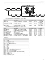
Monoblock Schematic Diagram:
kV
Inverter
filament
Inverter
{
{
T1
T2
T3
-mA
+kV
-kV
D1
D2
D3
D4
C1
C2
C3
C4
R1
R2
R3
R4
Tube
High voltage circuit comprises rectifier circuit and voltage doubler. High voltage circuit composes of high voltage
diode D1-D4, high voltage capacitor C1-C4. If output voltage from T1 is 60kV peak value the high voltage circuit
output 120kV to the tube.
The controller needs to get kV value and mA value from monoblock. KV sense circuit comprises high voltage
resistor R1, R4 and sense resistor R2, R3. The high voltage resistor value is 400M ohm, sense resistor is 20k ohm If
the voltage on the tube is 120kV the +kV output 3V and –kV output –3V. mA value is measured by serial resistor
between –mA and ground. So the mA voltage value is negative.
The tube is used to generate X-ray. This tube is a kind of double focus with fixed copper anode tube. It is suitable
for oil insulation generator.
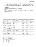
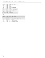
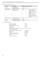
Analog signals KV_GND and MA_CAT of sealing board are the anode and cathode of mA current signal
respectively.
There are two temperature measurement circuits in sealing board. One’s output is analog signal OIL_TEMP.
The other’s output is connected/open status between THERMAL_SWITCH_A and THERMAL_SWITCH_B. If the
temperature of oil tank is higher than a preset threshold, the relationship between THERMAL_SWITCH_A and
THERMAL_SWITCH_B changes from connected to open.
Summary of Contents for Brivo OEC 715
Page 2: ......
Page 19: ...Chapter1 Introduction and Safety...
Page 41: ...Introduction and Safety 23 46 54 20 18 26...
Page 55: ...Chapter2 System Overview...
Page 137: ...Chapter3 Installation...
Page 212: ...Chapter4 Calibration...
Page 275: ...Brivo OEC 715 785 865 Mobile C Arm X Ray Product Service Manual 4 64...
Page 284: ...Chapter5 Software...
Page 326: ...Software 5 43 2 Click on install to continue 3 Click Next to continue...
Page 335: ...Chapter6 Troubleshooting...
Page 408: ...Chapter7 Replacement...
Page 418: ...Replacement 7 11 166...
Page 488: ...Chapter8 Periodic Maintenance...
Page 502: ...Periodic Maintenance 8 15...
Page 505: ...Chapter9 Technical Reference...
Page 521: ...Technical Reference 9 17 Vertical configuration 1 5m Vertical configuration 1m...
Page 526: ...11 Appendix System Schematics...

