Replacement
7-33
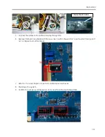
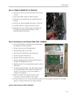
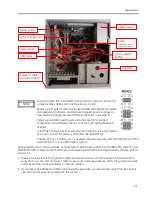
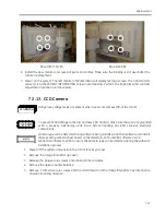
Shorten the left 2 pins (pin 1-2) of jumper S5 on CCB
board for collimator 5417680.
Shorten the right 2 pins (pin 2-3) of jumper S5 on CCB
board for collimator kit 5075984.
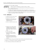
Fasten the screws of collimator cover with the torque to 1.04Nm.
German regulatory required that the collimator has
to be visible on two sides of the image, which are not
opposite. For the system installed in German, adjust
collimator iris until the collimator meet the
requirement as below.
7.3.9.
PWAs
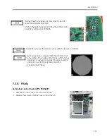
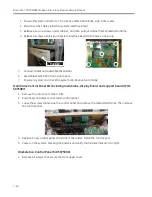
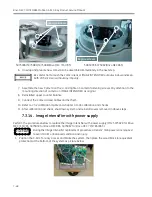
Collimator Control Board (P/N: 5085603)
1.
Remove the rear cover of the C-Arm console.
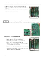
2.
Release the screws of e-Box cover and remove it.
Summary of Contents for Brivo OEC 715
Page 2: ......
Page 19: ...Chapter1 Introduction and Safety...
Page 41: ...Introduction and Safety 23 46 54 20 18 26...
Page 55: ...Chapter2 System Overview...
Page 137: ...Chapter3 Installation...
Page 212: ...Chapter4 Calibration...
Page 275: ...Brivo OEC 715 785 865 Mobile C Arm X Ray Product Service Manual 4 64...
Page 284: ...Chapter5 Software...
Page 326: ...Software 5 43 2 Click on install to continue 3 Click Next to continue...
Page 335: ...Chapter6 Troubleshooting...
Page 408: ...Chapter7 Replacement...
Page 418: ...Replacement 7 11 166...
Page 488: ...Chapter8 Periodic Maintenance...
Page 502: ...Periodic Maintenance 8 15...
Page 505: ...Chapter9 Technical Reference...
Page 521: ...Technical Reference 9 17 Vertical configuration 1 5m Vertical configuration 1m...
Page 526: ...11 Appendix System Schematics...

