System Overview
2-15
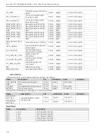
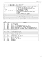
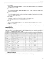
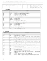
TP6
CPLD_INTLC_BRD_A
Interlock board signal
TP7
CPLD_INTLC_CABLE_A Interlock cable signal
TP8
AC Output of main transformer secondary side voltage divider
TP9
DC output of line gain in RMS-DC conversion circuit
TP10
The reference point of under/over voltage protection circuit
TP11-TP15
Reserved test points for debug for CPLD
TP16
SIB_INTLC_BRD
Interlock board signal for SIB board
TP18
DC output of main transformer secondary voltage RMS-DC
conversion
TP19
DC output of follower in RMS-DC conversion
TP20
Over voltage test point in start-up process
TP21
Over voltage test point in normal operation process
TP22
Under voltage test point in start-up process
TP23
Under voltage test point in normal operation process
TP24
GNDA
Reference point for analog circuit
TP25
GNDA
Reference point for analog circuit
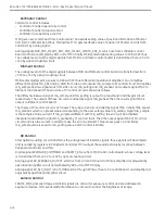
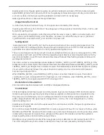
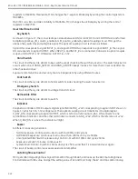
LEDs:
Name
Color
Description
HL1
Green
+3.3V power indicator
HL2
Green
+5V power indicator
HL4
Red
Secondary side over voltage fault indicator in start up process
HL5
Red
Secondary side under voltage fault indicator in start up process
HL6
Red
Secondary side voltage under voltage fault indicator in normal operation process
HL7
Red
Secondary side voltage over voltage fault indicator in normal operation process
HL8
Green
+12V power indicator
HL9
Green
Reset status indicator
HL10
Green
Interlock cable status indicator
HL11
Green
Interlock board status indicator
HL14
Green
UPS output state signal
HL16
Green
Mainframe power status indicator
HL17
red
+12V error status indicator
HL18
Green
Interlock cable lock status indicator
HL19
Green
PDU connect2 status indicator
HL20
red
RDY error status indicator
HL22
Green
PDU connect status indicator
HL3
Green
For Debug only
HL12
Green
For Debug only
Summary of Contents for Brivo OEC 715
Page 2: ......
Page 19: ...Chapter1 Introduction and Safety...
Page 41: ...Introduction and Safety 23 46 54 20 18 26...
Page 55: ...Chapter2 System Overview...
Page 137: ...Chapter3 Installation...
Page 212: ...Chapter4 Calibration...
Page 275: ...Brivo OEC 715 785 865 Mobile C Arm X Ray Product Service Manual 4 64...
Page 284: ...Chapter5 Software...
Page 326: ...Software 5 43 2 Click on install to continue 3 Click Next to continue...
Page 335: ...Chapter6 Troubleshooting...
Page 408: ...Chapter7 Replacement...
Page 418: ...Replacement 7 11 166...
Page 488: ...Chapter8 Periodic Maintenance...
Page 502: ...Periodic Maintenance 8 15...
Page 505: ...Chapter9 Technical Reference...
Page 521: ...Technical Reference 9 17 Vertical configuration 1 5m Vertical configuration 1m...
Page 526: ...11 Appendix System Schematics...


