Brivo OEC 715/785/865 Mobile C-Arm X-Ray Product Service Manual
4-56
b.
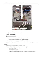
Disconnect Camera Cables.
c.
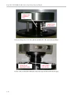
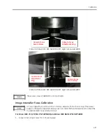
Reinstall the I.I. Power Supply and connect cables between power supply and I.I.
d.
Install counter weight.
e.
Connect Camera Head Cable, and make sure to tighten the securing screw.
f.
Assemble the I.I. cover.
g.
Power on the system.
Ensure the cable tightly connect to the I.I. Power Supply. Virtual connection will lead to no
image or image vibration in Fluoro.
4.6.9.
Shading Correction Check and Calibration
Shading Correction Calibration Check:
1.
Set to Normal mode, Auto Technique On.
2.
Take a Shot.
3.
Turn on the Automatic Brightness& Contrast.
4.
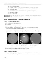
Keep the brightness level and manually increase Contrast Level to see well on Brightness
uniformity. Adjust the brightness level if necessary.
5.
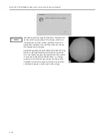
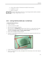
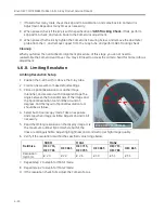
Pass if you see the brightness uniformity is good enough. For example the 1st image shows the
good brightness uniformity, and the 2nd image, 3rd image shows the brightness uniformity is not
good.
1
st
image(good example)
2
nd
image (Margin is darker
than center ) brightness
3
rd
image (brightness of
margin is brighter than
center)
6.
If you fail in step 5, need perform Shading Correction Calibration.
Shading Correction Calibration:
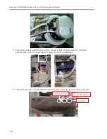
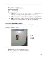
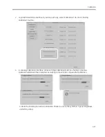
1.
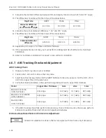
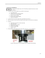
Before calibration, make sure there is no object in the image field, and the C-arm position is up-
down position with II vertically above tube.
Summary of Contents for Brivo OEC 715
Page 2: ......
Page 19: ...Chapter1 Introduction and Safety...
Page 41: ...Introduction and Safety 23 46 54 20 18 26...
Page 55: ...Chapter2 System Overview...
Page 137: ...Chapter3 Installation...
Page 212: ...Chapter4 Calibration...
Page 275: ...Brivo OEC 715 785 865 Mobile C Arm X Ray Product Service Manual 4 64...
Page 284: ...Chapter5 Software...
Page 326: ...Software 5 43 2 Click on install to continue 3 Click Next to continue...
Page 335: ...Chapter6 Troubleshooting...
Page 408: ...Chapter7 Replacement...
Page 418: ...Replacement 7 11 166...
Page 488: ...Chapter8 Periodic Maintenance...
Page 502: ...Periodic Maintenance 8 15...
Page 505: ...Chapter9 Technical Reference...
Page 521: ...Technical Reference 9 17 Vertical configuration 1 5m Vertical configuration 1m...
Page 526: ...11 Appendix System Schematics...

