Brivo OEC 715/785/865/865 Mobile C-Arm X-Ray Product Service Manual
2-22
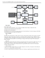
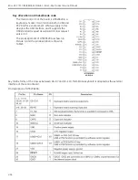
registers in MAX6954. Meanwhile, MCU changes the 7-segent LED display by writing the control registers in
MAX6954.
MAX7301 is a LED controller. Similarly to MAX6954, MCU changes the LED display by writing the control
registers in MAX7301.
User Interface Control
Key Switch
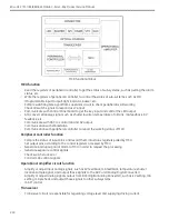
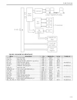
As shown in Figure 17, the connected/open status between ON (or X-RAY OFF) and COMMON is transformed
to digital signal Exp_lift_column_enable (or Lift_column_enable) by optical coupling circuit. MCU get the
status of key switch by sampling this signal. The optical coupling circuit is shown as follows.
Signal ON corresponds to signal INPUT_A, and signal COMMON corresponds to signal INPUT_B. Then signal
ON corresponds to signal OUTPUT. When INPUT_A and INPUT_B are connected, transistor in optical coupler
is open and OUTPUT is 0V. Otherwise, OUTPUT is +3.3V.
Hand Switch
The circuit and theory are similar to key switch except checking the switch stuck error. The switch stuck error
occurs when one of HAND_SWITCH and HAND_SECURITY keeps inactive for more than 10 seconds after the
other has been active.
Exposure command line and security line are independent by using different routes.
Foot Switch
The circuit and theory are similar to hand switch include checking the switch stuck error.
Emergency Switch
The circuit and theory are similar to voltage transmit circuit.
Removable Filter
The circuit and theory are similar to switch.
Indicator
Peripheral controller of MCB outputs digital signal IND24V corresponding to signal INPUT shown in
Figure 17, which is 0V/+3.3V voltage level. Then optical coupling circuit transforms it to digital signal
X_RAY_ON corresponding to signal OUTPUT, which is 12mA current. Signal X_RAY_ON connects to one
termination of indicator, and the other termination connects to GND_+24V, which is the reference of +24V.
When X_RAY_ON is active, the indicator will light.
Buzzer
6 different tones are generated.
- Normal exposure: continuous Du-Du-Du with du 100ms and cycle 1s
- HLF/RAD/DS exposure: continuous Du-Du-Du with du 100ms and cycle 500ms
- Uncompleted XRAY (switch release early): Di-Di-Di-Di with Di 100ms and cycle 250 ms
- Exposure exceeds 5 minutes: continuous Di
- System Fault: Di-Di-Di-Di with Di 100ms and cycle 250 ms and then 1s interval and over again
The circuit of buzzer control uses audio operational amplifier.
Auto Brightness Control
MCU gets IBS (Image Brightness Signal) from WKS through RS485, and looks up the ABC (Auto Brightness
Control) table with IBS value, and get the setting value of kV and mA. Finally, the kV and mA control analog
Summary of Contents for Brivo OEC 715
Page 2: ......
Page 19: ...Chapter1 Introduction and Safety...
Page 41: ...Introduction and Safety 23 46 54 20 18 26...
Page 55: ...Chapter2 System Overview...
Page 137: ...Chapter3 Installation...
Page 212: ...Chapter4 Calibration...
Page 275: ...Brivo OEC 715 785 865 Mobile C Arm X Ray Product Service Manual 4 64...
Page 284: ...Chapter5 Software...
Page 326: ...Software 5 43 2 Click on install to continue 3 Click Next to continue...
Page 335: ...Chapter6 Troubleshooting...
Page 408: ...Chapter7 Replacement...
Page 418: ...Replacement 7 11 166...
Page 488: ...Chapter8 Periodic Maintenance...
Page 502: ...Periodic Maintenance 8 15...
Page 505: ...Chapter9 Technical Reference...
Page 521: ...Technical Reference 9 17 Vertical configuration 1 5m Vertical configuration 1m...
Page 526: ...11 Appendix System Schematics...

