Introduction and Safety
35
CAUTION
11.
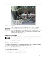
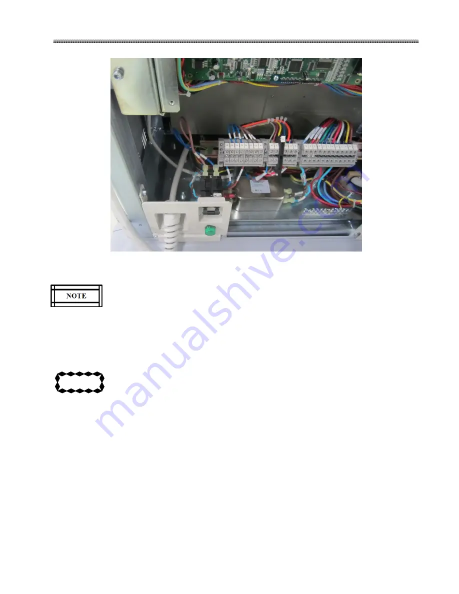
Power is now locked out.
In the event service will continue into another day, and/or the machine will cause a
hazard if reenergized after the authorized employee leaves the location, leave the A/C
cord cover installed with a “transition” lock and yellow tag attached.
If more than authorized employee is going to conduct service on the same system, at the
same time, multiple locking devices must be employed and each authorized employee
must adhere to the entire LOTO procedure.
Gravitational/mechanical energy
By removing the following components, unexpected gravitational energy can be released.
Removing the X-Ray tube, image intensifier, or the C weldment can cause the rear of the
C-arm to tilt and hit the floor. Place a block of wood under the rear of the C-arm to
prevent tilting crush hazard.
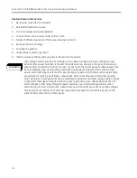
Testing and Positioning During Service
In the event that lockout/tagout devices must be temporarily removed from the energy isolating devices,
for testing or positioning purposes, the following sequence shall be followed:
1.
Clear the machine of tools and materials.
2.
Ensure that all employees/individuals in area are safely positioned or removed.
3.
Remove energy control measures.
4.
Energize system and proceed with testing or positioning.
5.
De-energize system and reapply energy control measure.
Summary of Contents for Brivo OEC 715
Page 2: ......
Page 19: ...Chapter1 Introduction and Safety...
Page 41: ...Introduction and Safety 23 46 54 20 18 26...
Page 55: ...Chapter2 System Overview...
Page 137: ...Chapter3 Installation...
Page 212: ...Chapter4 Calibration...
Page 275: ...Brivo OEC 715 785 865 Mobile C Arm X Ray Product Service Manual 4 64...
Page 284: ...Chapter5 Software...
Page 326: ...Software 5 43 2 Click on install to continue 3 Click Next to continue...
Page 335: ...Chapter6 Troubleshooting...
Page 408: ...Chapter7 Replacement...
Page 418: ...Replacement 7 11 166...
Page 488: ...Chapter8 Periodic Maintenance...
Page 502: ...Periodic Maintenance 8 15...
Page 505: ...Chapter9 Technical Reference...
Page 521: ...Technical Reference 9 17 Vertical configuration 1 5m Vertical configuration 1m...
Page 526: ...11 Appendix System Schematics...

