

Calibration
4-15
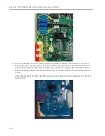
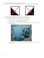
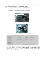
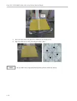
5.
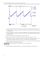
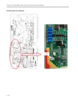
Change and set the multimeter to DC voltage mode. Connect multimeter to TP7 and TP1 (GND) on
MCB board. Take fluoro exposure and check the voltage is -0.8±0.05V, if not, adjust POT7 on MCB
board, anticlockwise rotation will increase the voltage value.
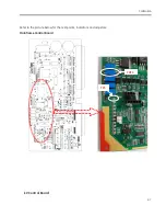
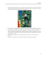
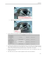
6.
Remove jumper on J5 of MCB board. Take fluoro exposure and check the voltage of TP7 on MCB
is -0.8V±0.05V, if not adjust POT5 on MCB board,clockwise rotation will increase the voltage value.
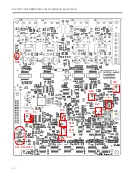
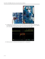
7.
Remove jumper J46. Change and set the multimeter to DC mA mode. Connect multimeter to
TP222 (+) and TP210 (-) on extend board. Take fluoro exposure, check the mA value is 2.1±0.05mA,
if not adjust POT7 on MCB board, clockwise rotation will increase the current. Remove multimeter
and install jumper to J46.
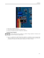
8.
If FDB is Rev 10 or higher version (PCB blue printed), perform step 9-11. If not, go to step 12
directly.
9.
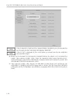
Set switch J7 to large position and confirm that the light of HL3(FIL_SEL) illuminates.
Summary of Contents for Brivo OEC 715
Page 2: ......
Page 19: ...Chapter1 Introduction and Safety...
Page 41: ...Introduction and Safety 23 46 54 20 18 26...
Page 55: ...Chapter2 System Overview...
Page 137: ...Chapter3 Installation...
Page 212: ...Chapter4 Calibration...
Page 275: ...Brivo OEC 715 785 865 Mobile C Arm X Ray Product Service Manual 4 64...
Page 284: ...Chapter5 Software...
Page 326: ...Software 5 43 2 Click on install to continue 3 Click Next to continue...
Page 335: ...Chapter6 Troubleshooting...
Page 408: ...Chapter7 Replacement...
Page 418: ...Replacement 7 11 166...
Page 488: ...Chapter8 Periodic Maintenance...
Page 502: ...Periodic Maintenance 8 15...
Page 505: ...Chapter9 Technical Reference...
Page 521: ...Technical Reference 9 17 Vertical configuration 1 5m Vertical configuration 1m...
Page 526: ...11 Appendix System Schematics...


