Calibration
4-45
d.
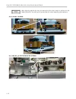
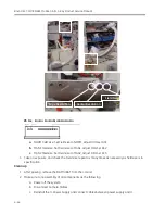
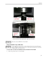
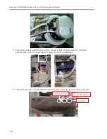
Connect Camera Cables, and make sure to tighten the secure screws.
e.
Assemble the I.I. cover.
f.
Power on the system.
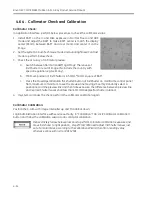
Ensure the cable tightly connect to the I.I. Power Supply. Virtual connection will lead to
no image or image vibration in Fluoro.
4.6.6.
Limiting Field Size (Collimator Iris Field Size)
Limiting Field Size Verification
1.
Create a new exam.
2.
Load a film cassette in the BAFT.
3.
Make sure the iris is opened completely.
4.
Make an exposure at
in Normal, MAG 1, MAG 2 for 5~10 seconds for each mode.
Take the three exposures on one sheet of film. Note: to select the Film MAG Mode, do the
following: Select
Manual - Fluoro,
then
Normal, MAG1 or MAG 2
.
5.
Remove the Film Cassette and develop the film.
6.
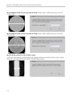
Measure the Normal field size diameter of the collimator iris as projected on the film at 45
°
and
135
°
angle with the ruler.
7.
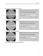
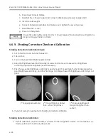
Set the system to Normal field size, and take an exposure.
8.
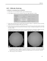
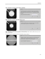
Measure, using the BAFT tick marks on the display monitor, the diameter of the circular image at
45
°
and 135
°
angle.
L1
L2
Summary of Contents for Brivo OEC 715
Page 2: ......
Page 19: ...Chapter1 Introduction and Safety...
Page 41: ...Introduction and Safety 23 46 54 20 18 26...
Page 55: ...Chapter2 System Overview...
Page 137: ...Chapter3 Installation...
Page 212: ...Chapter4 Calibration...
Page 275: ...Brivo OEC 715 785 865 Mobile C Arm X Ray Product Service Manual 4 64...
Page 284: ...Chapter5 Software...
Page 326: ...Software 5 43 2 Click on install to continue 3 Click Next to continue...
Page 335: ...Chapter6 Troubleshooting...
Page 408: ...Chapter7 Replacement...
Page 418: ...Replacement 7 11 166...
Page 488: ...Chapter8 Periodic Maintenance...
Page 502: ...Periodic Maintenance 8 15...
Page 505: ...Chapter9 Technical Reference...
Page 521: ...Technical Reference 9 17 Vertical configuration 1 5m Vertical configuration 1m...
Page 526: ...11 Appendix System Schematics...

