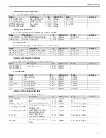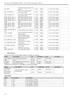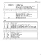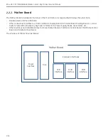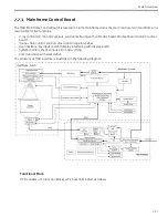
System Overview
2-9
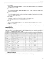
Power Output
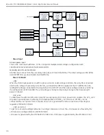
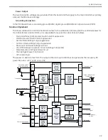
The two channel AC voltages are generated from this board and then apply to the main transformer primary
side and mainframe accordingly.
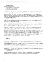
Grounding Connection
In the PDU board there is an analog ground (AGND), digital ground (DGND) and a protective earth (PE).
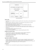
Function Implement
The Power distribution Unit (PDU) board is mounted in the workstation and provides the controlled power for
main transformer and mainframe. It is responsible for several main functions as follows.
-
Main transformer primary side Inrush Current Suppression
-
Mainframe side Inrush Current Suppression
-
Normal Mode Voltage Surge Suppression
-
Common Mode Voltage Surge Suppression
-
Gross over and under voltage lock-out
-
Line RMS Voltage Conversion Circuit & Voltage Comparator
-
State Detection and Signal Drive Circuit
-
The Intelligent Power Control Unit
-
UPS control logic
The power on board comes from the output of the start-up transformer and generates the necessary DC
power like +24V, +12V, +10V, +5V, +3.3V.
PJ2
Mainframe
Inrush
Current
Surge
suppression
PJ6
PJ1
Common
Mode
Voltage
Surge
suppression
Normal
Mode
Voltage
Surge
suppression
Primary
Inrush
Current
Surge
suppression
PJ7
PJ13
PJ3
PJ4
PJ5
Interlock
signal
detection
CMPTR
+12V signal
detection
Power
on/off
signal
detection
Intelligent
Power
Control
Unit
PJ8
RMS to DC
Convertion
Voltage
Comparator
Signal Drive
Circuit
PJ10
Mains power
Primary side of main
transformer
Secondary side of
main transformer
Mainframe side
Interlock signal
Computer
+12VDC signal
Power on/off button
WKS on/off ctrl
SIB board
Start up transformer
PJ12
Gross
over/under
voltage lock
J2
J3
200/220/230
/240V jumper
100/110
/120V jumper
24V/24V
+24V/+12V/+10V
/+5V/+3.3V
PJ14
UPS ctrl signal
UPS emergency
button
PE
PJ15
Summary of Contents for Brivo OEC 715
Page 2: ......
Page 19: ...Chapter1 Introduction and Safety...
Page 41: ...Introduction and Safety 23 46 54 20 18 26...
Page 55: ...Chapter2 System Overview...
Page 137: ...Chapter3 Installation...
Page 212: ...Chapter4 Calibration...
Page 275: ...Brivo OEC 715 785 865 Mobile C Arm X Ray Product Service Manual 4 64...
Page 284: ...Chapter5 Software...
Page 326: ...Software 5 43 2 Click on install to continue 3 Click Next to continue...
Page 335: ...Chapter6 Troubleshooting...
Page 408: ...Chapter7 Replacement...
Page 418: ...Replacement 7 11 166...
Page 488: ...Chapter8 Periodic Maintenance...
Page 502: ...Periodic Maintenance 8 15...
Page 505: ...Chapter9 Technical Reference...
Page 521: ...Technical Reference 9 17 Vertical configuration 1 5m Vertical configuration 1m...
Page 526: ...11 Appendix System Schematics...

