1-(35)
Basic Operations
Section 1-6
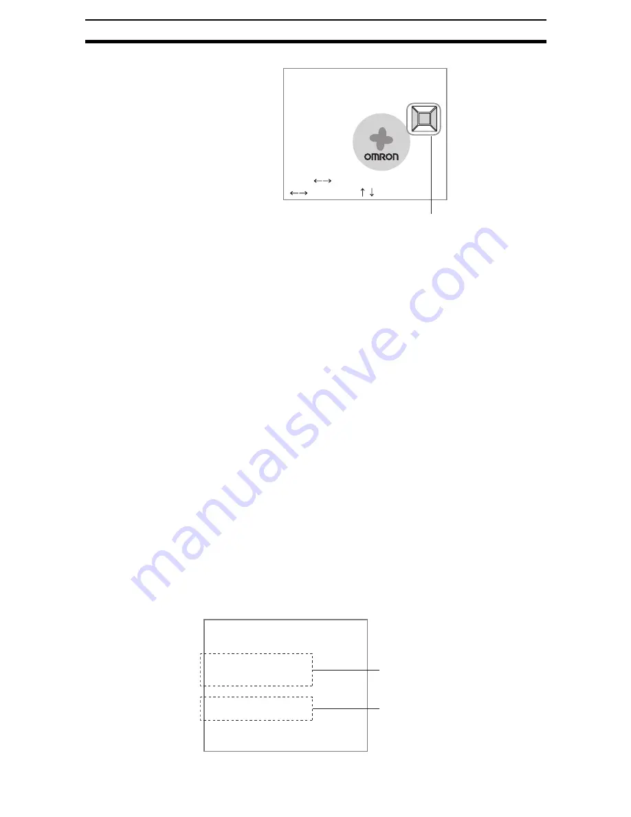
The Light Control Settings Screen will be displayed.
3.
Switch the sample pattern lighting level using the SHIFT+Left/Right Keys.
CHECK
For fine adjustment of light levels, move to the desired segment using the
Right and Left Keys and adjust the light level using the Up and Down Keys.
4.
Press the ENT Key.
The setting will be registered and the screen in (1.) will return.
CHECK
If all light adjustments are set to 5 or higher, there may be insufficient light
emitted if the distance between measurements is approximately 15 ms or less.
If this happens, set the light level to 4 or less.
Calibration
Calibration can be set to output the measurement results in physical units.
Set the relationship between the physical coordinates and the camera coordi-
nates to convert the measurement results from pixels to physical units, such
as
m
m, mm, or cm.
This section gives an outline only. Refer to 2-1 Inputting Camera Images for
details on calibration.
CHECK
To output measurement results in physical units, set Coordinate mode/Calibra-
tion to ON for each processing item.
If Calibration remains set to OFF, the default settings will remain, and mea-
surements using the Camera coordinates will be output.
1-6-1-2
Selecting the Camera
Up to 4 Cameras can be connected. The Select Camera setting is used to
select the Camera image that will be used for measurement.
CHECK
The Camera image selected here will be used for all subsequent unit mea-
surements. To switch to a different Camera part way through processing, use
the Switch Camera processing item. Other Camera images stored in the
image buffers can be imported to Image 0 and Image 1.
Light control(Camera0)
Lighting pattern5:27272
SFT+ :Sample
:Segment :Light volume
Graphic showing light level
0.Camera image
1.Density defect
2.Binary defect
3.Fine matching
4.Switch camera
5.Density defect
6Binary defect
0.Scn 0=SET=
The Camera image selected at
0. Camera image will be used
for measurement.
The Camera image selected
using 4. Switch camera will be
used for measurement.
Содержание F250-UME
Страница 2: ...80 SSOLFDWLRQ 6RIWZDUH 2SHUDWLRQ 0DQXDO 5HYLVHG HFHPEHU...
Страница 3: ...iii...
Страница 337: ...2 15 4 EC Defect Section 2 15 4 Press the ENT Key The settings will be registered and the screen in 1 will return...
Страница 531: ...2 23 4 ECM Search Section 2 23 4 Press the ENT Key The settings will be registered and the screen in 1 will return...
Страница 748: ...2 49 5 Display Line Display Box Display Circle and Display Cursor Section 2 49...
Страница 798: ...4 44 Memory Card Operations Section 4 6...
Страница 998: ...7 18 Menu Hierarchy Section 7 6...


