2-12-(25)
Detecting Binary Defects
Section 2-12
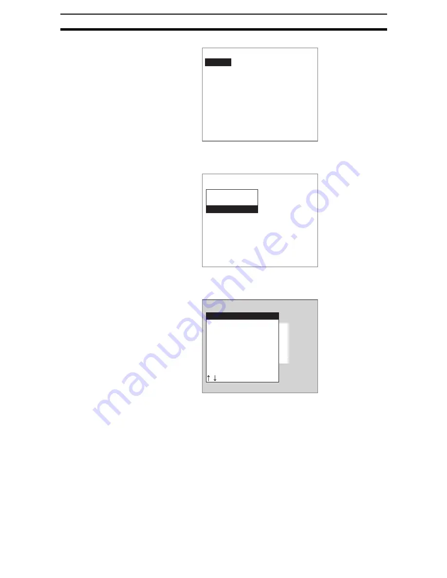
A list of region numbers will be displayed.
3.
Select the region number.
The selection of measurement methods will be displayed.
4.
Select Area (var. box).
The initial Area Var. Box Screen will be displayed.
5.
Select Binary.
The Binary Levels Settings Screen will be displayed.
The rest of the procedure is the same as outlined under
6HWWLQJWKH
%LQDU\/HYHO
.
SeeAlso
Refer to page 2-12-(4).
STEP 2: Setting Measurement Conditions
Set measurement conditions to measure the exterior of a measurement object
or to make the binary levels track the brightness of the measurement image.
The default for all settings is OFF.
SeeAlso
Refer to page 2-12-(10) for information on the fill profile and binary tracking
functions.
Select region
Region0
Region1
Region2
Region3
Region4
Region5
Region6
Region7
New registration(Region0)
Gravity and area
Gravity and axis
Area(var.box)
Region0(Area(var.box))
Binary
Measurement conditions
Left edge
Upper edge
Right edge
Lower edge
Reference registration
Judgement conditions
Содержание F250-UME
Страница 2: ...80 SSOLFDWLRQ 6RIWZDUH 2SHUDWLRQ 0DQXDO 5HYLVHG HFHPEHU...
Страница 3: ...iii...
Страница 337: ...2 15 4 EC Defect Section 2 15 4 Press the ENT Key The settings will be registered and the screen in 1 will return...
Страница 531: ...2 23 4 ECM Search Section 2 23 4 Press the ENT Key The settings will be registered and the screen in 1 will return...
Страница 748: ...2 49 5 Display Line Display Box Display Circle and Display Cursor Section 2 49...
Страница 798: ...4 44 Memory Card Operations Section 4 6...
Страница 998: ...7 18 Menu Hierarchy Section 7 6...


