Appendix - 124
MELSEC-Q
APPENDICES
INPUT TERMINAL
This is a pin connector wired by the user for
inputting data to the QD75 from an external
source. It is connected to the motor drive unit
or machine side.
This terminal is used to output the following.
•
DRIVE UNIT READY signal
•
START signal
•
STOP signal
, etc.
The input No. Xn is not directly related to the
program, so it is not used.
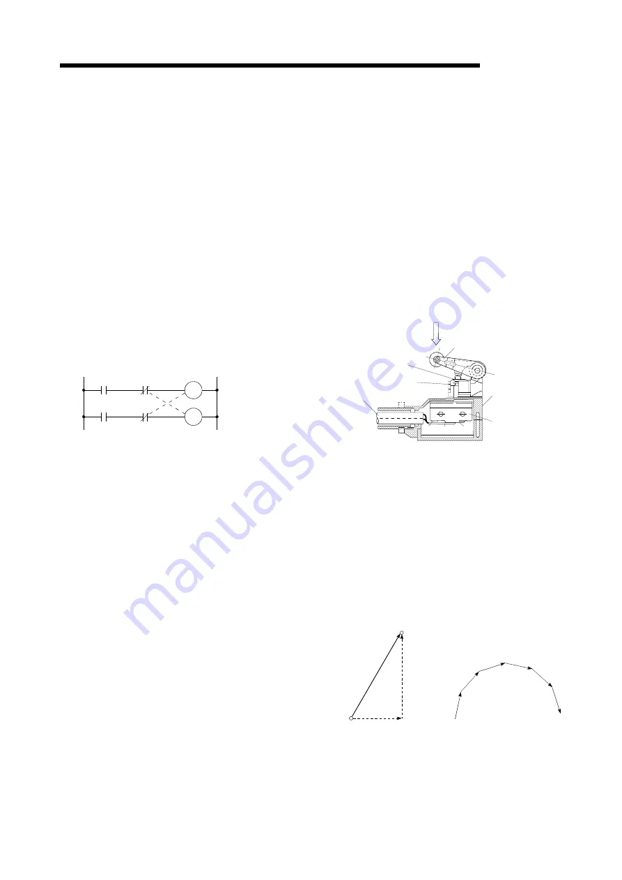
INTERLOCK
In this condition, the machine is blocked from
moving to the next operation until the
operation in progress is complete. This
function is used to prevent damage to devices
and malfunctioning.
Y1
Y0
Y0
Y1
Forward run
Reverse run
INTERPOLATION OPERATION
The simultaneous operation of multiple motors
to carry out a composite operation. Each motor
can be freely set with the positioning distance,
acceleration/deceleration time, speed, and
other factors, which are combined to move a
target in a straight line, circle, etc. Linear
interpolation and circular interpolation are
available. (The circular interpolation uses two
motors.)
INVERTER
This refers to a device to change a direct
current (DC) to an alternating current (AC).
The device actually changes the motor speed
by changing 50Hz or 60Hz of commercial
frequency to direct current once, then
changing it again to a 5 to 120Hz alternating
current and controlling the motor speed.
JOG
Jog. This refers to moving the tool little by
little. Inching.
Parameter setting is required to carry out JOG
operation.
kPPS
This is the abbreviation for "kilopulses per
second". 80kPPS equals 80,000 pulses per
second.
LIMIT SWITCH
This is a switch set to stop a moving object at
both ends, etc., of a movement device for
safety reasons.
A circuit is created in which the moving body
itself presses against the switch to activate the
contact and forcibly shut the power OFF. For
example, pressing on the actuator in the
drawing below activates the internal
microswitch. There are various other types.
NC NO COM
Push plunger
Actuator
Rubber cap
Lead
Case
Microswitch
LINEAR INTERPOLATION
This automatic operation simultaneously
operates two motors for the latitudinal (X) feed
and longitudinal (Y) feed to move a target in a
diagonal line for positioning. Three or four
motors can also be operated simultaneously.
The QD75 combines the operation of axis 1
through 4 for the linear interpolation. The same
positioning data No. must be used for the
setting. Refer to the term "INTERPOLATION
OPERATION".
No.9
No.8
No.1
2
3
4
5
6
7
Longitudinal
feed
Latitudinal feed
LOAD INERTIA RATIO
GDL
2
/GDM
2
Refer to "GD
2
".
Summary of Contents for Melsec-Q QD75D1
Page 1: ......
Page 2: ......
Page 22: ...A 20 MEMO ...
Page 24: ...MEMO ...
Page 41: ...1 17 MELSEC Q 1 PRODUCT OUTLINE MEMO ...
Page 48: ...1 24 MELSEC Q 1 PRODUCT OUTLINE MEMO ...
Page 60: ...2 12 MELSEC Q 2 SYSTEM CONFIGURATION MEMO ...
Page 137: ...5 33 MELSEC Q 5 DATA USED FOR POSITIONING CONTROL MEMO ...
Page 232: ...5 128 MELSEC Q 5 DATA USED FOR POSITIONING CONTROL MEMO ...
Page 252: ...6 20 MELSEC Q 6 SEQUENCE PROGRAM USED FOR POSITIONING CONTROL ...
Page 253: ...6 21 MELSEC Q 6 SEQUENCE PROGRAM USED FOR POSITIONING CONTROL ...
Page 278: ...6 46 MELSEC Q 6 SEQUENCE PROGRAM USED FOR POSITIONING CONTROL MEMO ...
Page 292: ...MEMO ...
Page 436: ...9 120 MELSEC Q 9 MAJOR POSITIONING CONTROL MEMO ...
Page 464: ...10 28 MELSEC Q 10 HIGH LEVEL POSITIONING CONTROL MEMO ...
Page 638: ...14 24 MELSEC Q 14 DEDICATED INSTRUCTIONS MEMO ...
Page 647: ...15 9 MELSEC Q 15 TROUBLESHOOTING MEMO ...
Page 686: ...15 48 MELSEC Q 15 TROUBLESHOOTING MEMO ...
Page 839: ...Appendix 153 MELSEC Q APPENDICES 6 QD75D4N 90 23 27 4 12 98 4 46 Unit mm ...
Page 840: ...Appendix 154 MELSEC Q APPENDICES 7 QD75P1 QD75P2 QD75P4 27 4 23 98 90 4 46 unit mm ...
Page 841: ...Appendix 155 MELSEC Q APPENDICES 8 QD75D1 QD75D2 QD75D4 27 4 23 90 12 98 4 46 unit mm ...
Page 842: ...Appendix 156 MELSEC Q APPENDICES MEMO ...
Page 857: ......
Page 858: ......


