Appendix - 133
MELSEC-Q
APPENDICES
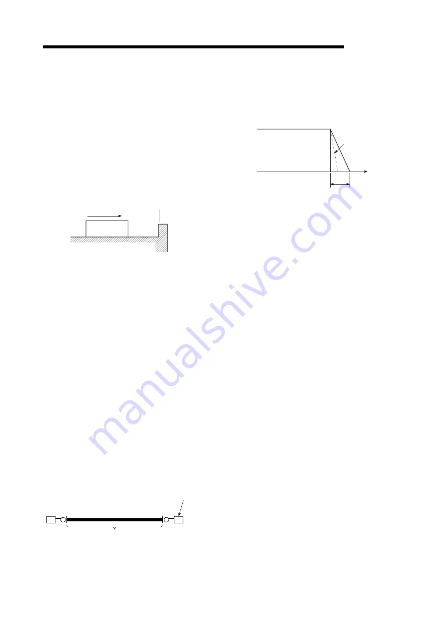
STOP WITH STOPPER
This is one machine OPR method. With this
method, a stopper is established at the OP,
and the operation is stopped when the
machine presses against it.
Motor burning would occur or the stopper
would be damaged if the machine were left in
that state. There are two methods to prevent
this; a timer can be used to shut OFF the
motor after a fixed time, or the motor can be
stopped by limiting sudden increase in the
motor torque when the machine presses
against the stopper.
Machine OPR
OP
Stopper
STROKE
The stroke is the variation in the operation by
the distance from a stopped state to the next
stopped state after a movement.
STROKE LIMIT
This is the range in which a positioning
operation is possible, or the range in which the
machine can be moved without damage
occurring.
(Movement outside this range is possible in
the manual operation.) For operations using a
worm gear, the stroke limit is determined by
the length of the screw. For operations using a
fixed-feed, it is determined by the max.
dimension to be cut.
The upper and lower limits are set in the
parameters, but a separate limit switch should
be established and an emergency stop circuit
outside the programmable controller should be
created. Refer to the term "LIMIT SWITCH".
Lower limit
0
Upper limit
Limit switch
for emergency
stop
Positioning possible in a 3m (9.84feet) range
3m (9.84feet)
SUDDEN STOP
A stop carried out in a shorter time than the
deceleration time designated in the
parameters.
Full speed
Sudden stop
Time
Deceleration time
TEACHING
When the positioning address is uncertain, or
gauging is required, this function is used by
the user to search for and teach the position to
the machine.
For example, complex addresses such as
drawings can be taught by tracing a model,
and the positioning operation can be
reproduced.
TORQUE CONTROL
In this function, a limit is established for the
resistance torque applied to the motor used for
positioning. The power is turned OFF if torque
exceeding that value is applied to the motor.
When excessive torque is applied to a motor, it
causes the current to suddenly increase. Motor
burning and other stress on the motor occurs,
and the life of the motor is shortened.
This function utilizes the sudden increase in
the torque when the machine OPR to issue a
command to stop the motor.
TORQUE LOOP MODE
Also called the current loop mode.
Refer to "POSITIONING LOOP MODE".
TORQUE RIPPLE
Torque width variations, deviations in the
torque.
Summary of Contents for Melsec-Q QD75D1
Page 1: ......
Page 2: ......
Page 22: ...A 20 MEMO ...
Page 24: ...MEMO ...
Page 41: ...1 17 MELSEC Q 1 PRODUCT OUTLINE MEMO ...
Page 48: ...1 24 MELSEC Q 1 PRODUCT OUTLINE MEMO ...
Page 60: ...2 12 MELSEC Q 2 SYSTEM CONFIGURATION MEMO ...
Page 137: ...5 33 MELSEC Q 5 DATA USED FOR POSITIONING CONTROL MEMO ...
Page 232: ...5 128 MELSEC Q 5 DATA USED FOR POSITIONING CONTROL MEMO ...
Page 252: ...6 20 MELSEC Q 6 SEQUENCE PROGRAM USED FOR POSITIONING CONTROL ...
Page 253: ...6 21 MELSEC Q 6 SEQUENCE PROGRAM USED FOR POSITIONING CONTROL ...
Page 278: ...6 46 MELSEC Q 6 SEQUENCE PROGRAM USED FOR POSITIONING CONTROL MEMO ...
Page 292: ...MEMO ...
Page 436: ...9 120 MELSEC Q 9 MAJOR POSITIONING CONTROL MEMO ...
Page 464: ...10 28 MELSEC Q 10 HIGH LEVEL POSITIONING CONTROL MEMO ...
Page 638: ...14 24 MELSEC Q 14 DEDICATED INSTRUCTIONS MEMO ...
Page 647: ...15 9 MELSEC Q 15 TROUBLESHOOTING MEMO ...
Page 686: ...15 48 MELSEC Q 15 TROUBLESHOOTING MEMO ...
Page 839: ...Appendix 153 MELSEC Q APPENDICES 6 QD75D4N 90 23 27 4 12 98 4 46 Unit mm ...
Page 840: ...Appendix 154 MELSEC Q APPENDICES 7 QD75P1 QD75P2 QD75P4 27 4 23 98 90 4 46 unit mm ...
Page 841: ...Appendix 155 MELSEC Q APPENDICES 8 QD75D1 QD75D2 QD75D4 27 4 23 90 12 98 4 46 unit mm ...
Page 842: ...Appendix 156 MELSEC Q APPENDICES MEMO ...
Page 857: ......
Page 858: ......


