8 - 17
MELSEC-Q
8 OPR CONTROL
8.2.7 OPR method (5): Count method1)
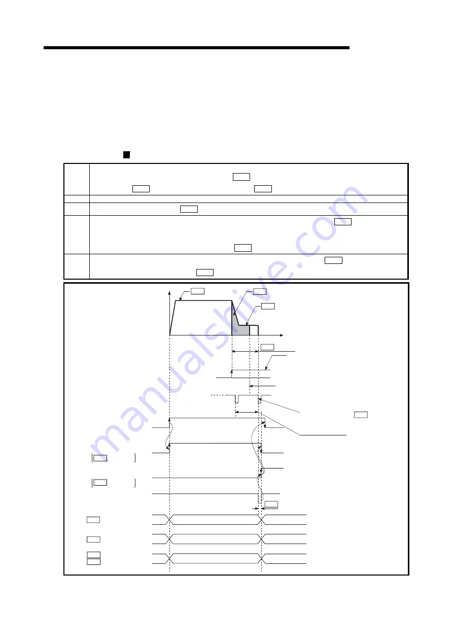
The following shows an operation outline of the "count method 1)" OPR method.
In the "count method 1)", machine OPR can be performed even in the following
situations:
•
when near-point dog is ON
•
after completion of a machine OPR
Operation chart
1)
The machine OPR is started.
(The machine begins the acceleration designated in "
Pr.51
OPR acceleration time selection", in the direction
designated in "
Pr.44
OPR direction". It then moves at the "
Pr.46
OPR speed" when the acceleration is completed.)
2)
The machine begins decelerating when the near-point dog ON is detected.
3)
The machine decelerates to the "
Pr.47
Creep speed", and subsequently moves at that speed.
4)
On detection of the first zero signal after the axis has traveled the movement amount set in "
Pr.50
Setting for the
movement amount after near-point dog ON" after near-point dog ON, the pulse output from the QD75 stops and the
"deviation counter clear output" is output to the drive unit.
(A "deviation counter clear signal output time" is set in
Pr.55
.)
5)
After a "deviation counter clear output" is output to the drive unit, the OPR complete flag
Md.31
Status: b4) turns from
OFF to ON, and the OPR request flag (
Md.31
Status: b3) turns from ON to OFF.
t
ON
1)
2)
3)
4) 5)
OFF
OPR speed
OFF
OFF
ON
Standby
OPR
Standby
Inconsistent
0
Movement amount
after near-point dog ON
Inconsistent
Value the machine moved is stored
OP address
Current feed value
V
Zero signal
Value of *1
Deviation counter clear output
Movement amount after near-point dog ON
Near-point dog
ON
OFF
*1
Creep speed
OPR request flag
OPR complete flag
Md.31
Md.31
Md.26
Md.34
Md.20
Md.21
Pr.46
Pr.47
Md.34
Machine feed value
Pr.50 Setting for the movement amount
after near-point dog ON
Leave sufficient distance from the zero point
position to the near-point dog OFF
Adjust the setting for the movement amount after
near-point dog ON to be as near as possible to
the center of the zero signal HIGH.
If the setting for the movement amount after
near-point dog ON falls within the zero signal,
there may be produced an error of one servomotor
rotation in the machine OPR stop position.
First zero signal after travel of the
movement amount set to " Pr. 50 Setting
for the movement amount after near-point
dog ON"
One servomotor rotation
Deviation counter clear
signal output time
Pr.55
Machine OPR start
(Positioning start signal)
[Y10,Y11,Y12,Y13]
Status: b3
Status: b4
Axis operation status
ON
Fig. 8.12 Count method1) machine OPR
Summary of Contents for Melsec-Q QD75D1
Page 1: ......
Page 2: ......
Page 22: ...A 20 MEMO ...
Page 24: ...MEMO ...
Page 41: ...1 17 MELSEC Q 1 PRODUCT OUTLINE MEMO ...
Page 48: ...1 24 MELSEC Q 1 PRODUCT OUTLINE MEMO ...
Page 60: ...2 12 MELSEC Q 2 SYSTEM CONFIGURATION MEMO ...
Page 137: ...5 33 MELSEC Q 5 DATA USED FOR POSITIONING CONTROL MEMO ...
Page 232: ...5 128 MELSEC Q 5 DATA USED FOR POSITIONING CONTROL MEMO ...
Page 252: ...6 20 MELSEC Q 6 SEQUENCE PROGRAM USED FOR POSITIONING CONTROL ...
Page 253: ...6 21 MELSEC Q 6 SEQUENCE PROGRAM USED FOR POSITIONING CONTROL ...
Page 278: ...6 46 MELSEC Q 6 SEQUENCE PROGRAM USED FOR POSITIONING CONTROL MEMO ...
Page 292: ...MEMO ...
Page 436: ...9 120 MELSEC Q 9 MAJOR POSITIONING CONTROL MEMO ...
Page 464: ...10 28 MELSEC Q 10 HIGH LEVEL POSITIONING CONTROL MEMO ...
Page 638: ...14 24 MELSEC Q 14 DEDICATED INSTRUCTIONS MEMO ...
Page 647: ...15 9 MELSEC Q 15 TROUBLESHOOTING MEMO ...
Page 686: ...15 48 MELSEC Q 15 TROUBLESHOOTING MEMO ...
Page 839: ...Appendix 153 MELSEC Q APPENDICES 6 QD75D4N 90 23 27 4 12 98 4 46 Unit mm ...
Page 840: ...Appendix 154 MELSEC Q APPENDICES 7 QD75P1 QD75P2 QD75P4 27 4 23 98 90 4 46 unit mm ...
Page 841: ...Appendix 155 MELSEC Q APPENDICES 8 QD75D1 QD75D2 QD75D4 27 4 23 90 12 98 4 46 unit mm ...
Page 842: ...Appendix 156 MELSEC Q APPENDICES MEMO ...
Page 857: ......
Page 858: ......


