DMA Controller
CPU
DMA channel 0
DMA channel 15
Ch1
PSA Sig Reg
CRC Value Reg
Ch4
CRC Value Reg
PSA Sig Reg
DMA channel p
DMA channel q
.DMA Request Event Sync.
CRC
Controller
SW
DMA Req
HW DMA Req
Memory System
Sector 1
Sector 2
Sector n
Sector 1 CRC value
Sector 2 CRC value
Sector n CRC value
one
block
DMA Controller
Timer
DMA channel 0
DMA channel 15
Ch1
PSA Sig Reg
CRC Value Reg
Ch4
CRC Value Reg
PSA Sig Reg
DMA channel p
DMA channel q
.DMA Request Event Sync.
CRC
Controller
HW
DMA Req
HW DMA Req
Memory System
Sector 1
Sector 2
Sector n
Sector 1 CRC value
Sector 2 CRC value
Sector n CRC value
one
block
Module Operation
632
SPNU563A – March 2018
Copyright © 2018, Texas Instruments Incorporated
Cyclic Redundancy Check (CRC) Controller Module
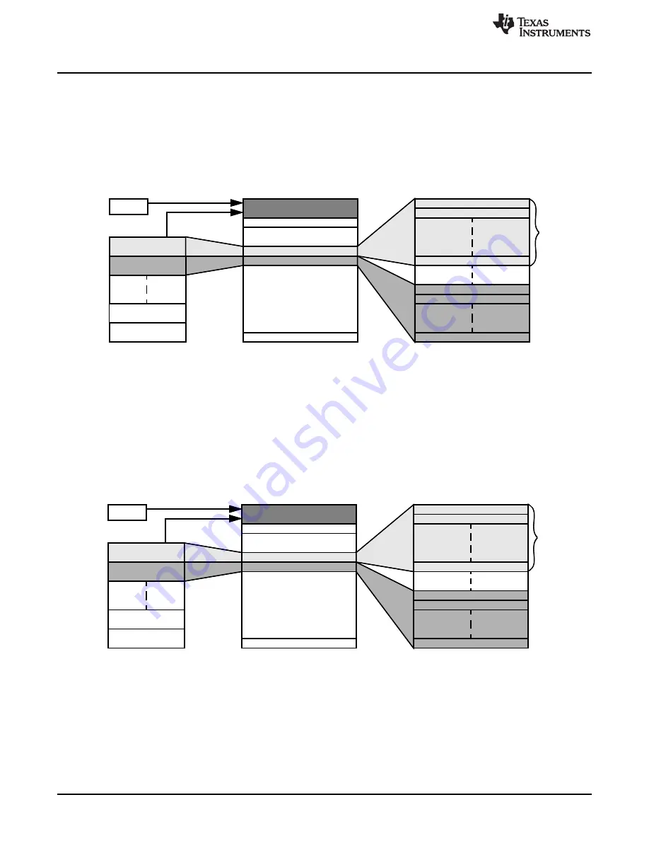
The total size of the memory system to be examined is also programmed in the respective transfer count
register inside DMA module. The DMA transfer count register is divided into two parts. They are element
count and frame count. Note that an HW DMA request can be programmed to trigger either one frame or
one entire block transfer. In
, an HW DMA request from a timer is used as a trigger source to
initiate DMA transfer. If all four CRC channels are active in AUTO mode then a total of four DMA requests
would be generated by CRC Controller.
Figure 18-3. AUTO Mode Using Hardware Timer Trigger
18.2.7.2 AUTO Mode Using Software Trigger
The data patterns transfer can also be initiated by software. CPU can generate a software DMA request to
activate the DMA channel to transfer data patterns from source memory system to the PSA Signature
Register. To generate a software DMA request CPU needs to set the corresponding DMA channel in the
DMA software trigger register. Note that just one software DMA request from CPU is enough to complete
the entire data patterns transfer for all sectors. See
for an illustration.
Figure 18-4. AUTO Mode With Software CPU Trigger


