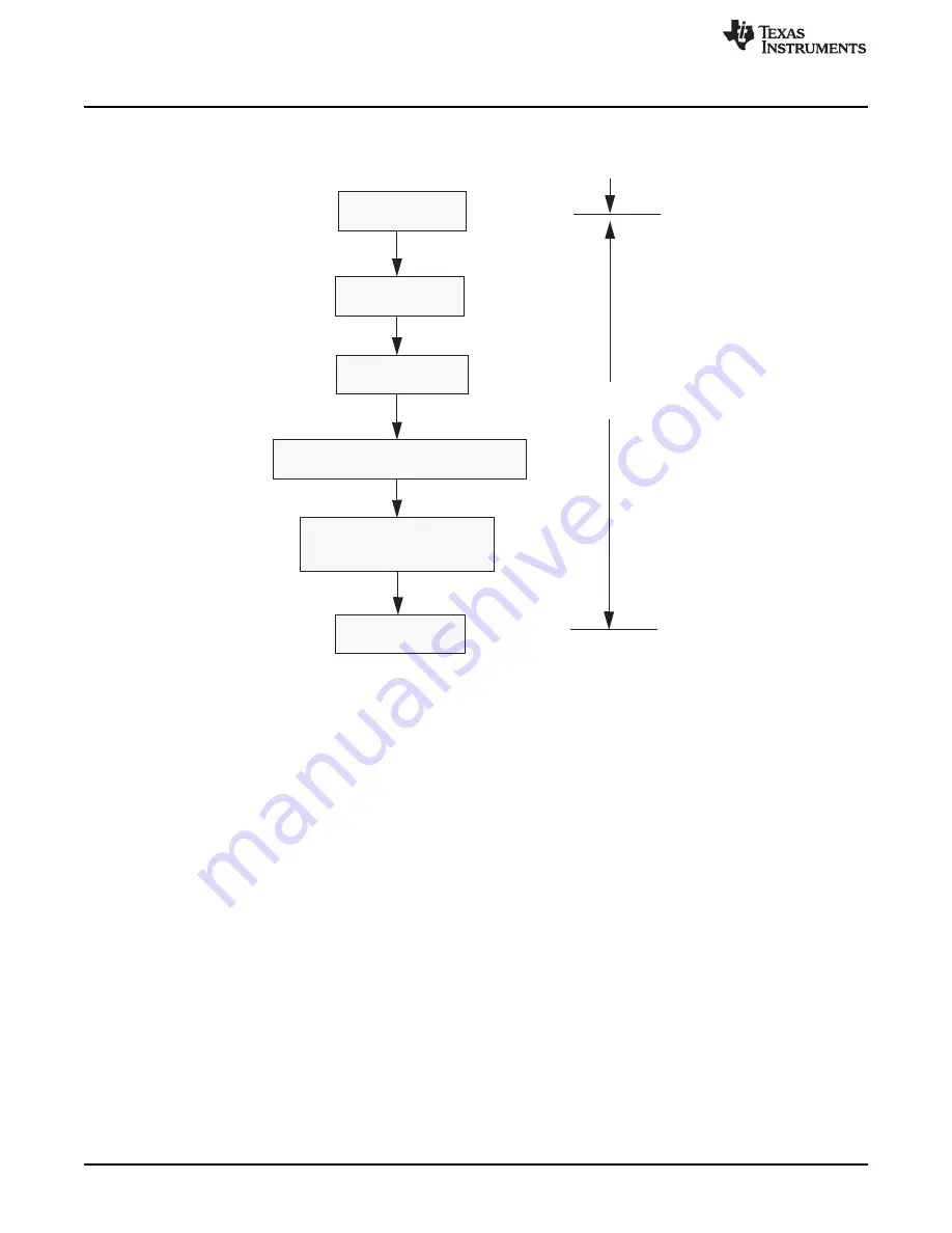
Set Init = 1
Set CCE = 1
Wait for Init =1
Write Bit timing values into BTR
Clear CCE and Init
Wait for Init =0
CCE = 0 , Init =0
Normal Mode
Initialization Mode
Normal Mode
CAN Module Configuration
1426
SPNU563A – March 2018
Copyright © 2018, Texas Instruments Incorporated
Controller Area Network (DCAN) Module
Figure 27-3. CAN Bit-timing Configuration
Step 1:
Enter “initialization mode” by setting the Init (Initialization) bit in the CAN Control Register.
While the Init bit is set, the message transfer from and to the CAN bus is stopped, and the status of the
CAN_TX output is recessive (high).
The CAN error counters are not updated. Setting the Init bit does not change any other configuration
register.
Also note that the CAN module is also in initialization mode on hardware reset and during Bus-Off.
Step 2:
Set the CCE (Configure Change Enable) bit in the CAN Control Register.
The access to the Bit Timing Register for the configuration of the Bit timing is enabled when both Init and
CCE bits in the CAN Control Register are set.
Step 3:
Wait for the Init bit to get set. This would make sure that the module has entered “Initialization
mode”.
Step 4:
Write the Bit-Timing values into the Bit-Timing Register (BTR).
Refer to
for BTR value calculation for a given bit-timing.
Step 5:
Clear the CCE bit followed by Init bit.
Step 6:
Wait for the Init bit to clear. This would make sure that the module has come out of “initialization
mode”.
After step 6 (Init bit cleared), the module will attempt a synchronization on the CAN bus, provided that the
BTR settings are meeting the CAN bus parameters.


