xxviii
Precauti
on
s for
Safe
U
se
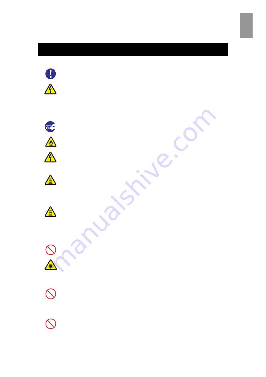
Precautions for Safe Use
Requirements for power outlets
Use a grounding 2-pole plug-in power outlet. Outlets of any other types
would cause an electric shock or fire.
In order to prevent an electric shock, connect the outlet’s grounding
electrode to a grounding terminal installed by a qualified electrician. Without
connection to the grounding terminal, an electric shock can occur in the
event of a failure in power supply modules.
Plugging and unplugging
When inserting the power plug into the electrical outlet or removing it, be
sure to hold the plug section. Do not pull the cable; it can partially break the
wire, overheat the broken part and lead to a fire.
Be sure to handle the power plug with a dry hand when inserting or
removing it into/from the outlet. Handling it with a moistened hand can cause
an electric shock.
Cover for the power supply module
When a power supply module is in operation, the cover and handle get hot. Be
careful when replacing a failed module. You can get burned.
High temperature at the 10GBASE-R transceiver
The 10GBASE-R transceiver in the 10Gbps LAN switch module gets hot in
operation. To remove the transceiver, therefore, allow at least approximately 5
minutes after the power supply for the 10Gbps LAN switch module is turned off
from the management module. Failure to do so can cause you to get burned.
Laser beam
On this product, a Class 1 laser product is installed. Do not look directly at
the laser beam. Do not look at the laser beam using an optical instrument.
Under the laser module cover, a laser beam is being emitted. Do not
remove the cover of an unused board.
Plastic bags for packaging
To avoid danger of suffocation, do not leave plastic bags, such as air bubble
cushioning for packaging, within reach of children.
Requirements for the product
Install the product on a fixed rack. Do not lean against the product or stand on it.
Do not install the product in a place with weak floors and walls.
Do not subject the product to excessive vibration. That can drop and fall the
product, leading to failure.
Summary of Contents for Compute Blade 2000
Page 1: ...MK 99BDS2K001 16 Hitachi Compute Blade 2000 User s Guide ...
Page 42: ...xlii Precautions for Safe Use Rear View of A1 A2 Chassis ...
Page 43: ...xliii Precautions for Safe Use Rear View of A2 Chassis ...
Page 44: ...xliv Precautions for Safe Use Server Blade ...
Page 45: ...xlv Precautions for Safe Use I O Slot Expansion Unit ...
Page 46: ...xlvi Precautions for Safe Use I O Module ...
Page 47: ...xlvii Precautions for Safe Use AC Power Input Module ...
Page 51: ...li How to Use the Manuals This page is intentionally left blank ...
Page 61: ...10 1 Before Use ...
Page 64: ...13 2 How to Use the System Equipment Rear view of A1 chassis Rear view of A2 chassis ...
Page 93: ...42 2 How to Use the System Equipment ...
Page 123: ...72 3 Connecting the System Equipment and Powering On ...
Page 272: ...221 5 Server Blade Setup 3 Check Del and click Go The following screen appears 4 Click Yes ...
Page 345: ...294 5 Server Blade Setup 12 Click Next The following screen appears ...
Page 351: ...300 5 Server Blade Setup 3 Check Delete and click Go The following screen appears 4 Click Yes ...
Page 426: ...375 5 Server Blade Setup 3 Check Delete and click Go The following screen appears 4 Click Yes ...
Page 430: ...379 5 Server Blade Setup 3 Click Go Hotspare is set to the specified hard disk ...
Page 479: ...428 5 Server Blade Setup ...
Page 717: ...666 6 Management Module Settings Details of a physical partition ...
Page 722: ...671 6 Management Module Settings Server blade details view ...
Page 723: ...672 6 Management Module Settings ...
Page 732: ...681 6 Management Module Settings Management module details view ...
Page 745: ...694 6 Management Module Settings Optional Physical WWN list view ...
Page 748: ...697 6 Management Module Settings Optional Physical WWN initialization view ...
Page 751: ...700 6 Management Module Settings ...
Page 754: ...703 6 Management Module Settings Power status details view ...
Page 767: ...716 6 Management Module Settings ...
Page 768: ...717 6 Management Module Settings ...
Page 769: ...718 6 Management Module Settings ...
Page 814: ...763 6 Management Module Settings Power status trend view partition ...
Page 817: ...766 6 Management Module Settings Access log display view ...
Page 819: ...768 6 Management Module Settings WWN change log display view ...
Page 879: ...828 7 Configuring the LAN Switch Module Link aggregation adding editing screen ...
Page 899: ...848 8 Configuring the 10 Gb DCB Switch Module ...
Page 919: ...868 10 Configuring the Fibre Channel Switch Module ...
Page 1535: ...1484 12 Logical partitioning manager ...
Page 1877: ...1826 14 14 When You Need Help ...
Page 1925: ...16 Glossary ...


