1831
15
15
Maintena
nce
and R
epla
cement
P
ar
ts
Service life limited parts
The following parts have respective product life and their performance will be degraded or worn
out while in use. Replace them periodically with new parts. For prices and delivery time, consult
your reseller.
For details on the options not covered here, see the manuals
supplied with those options.
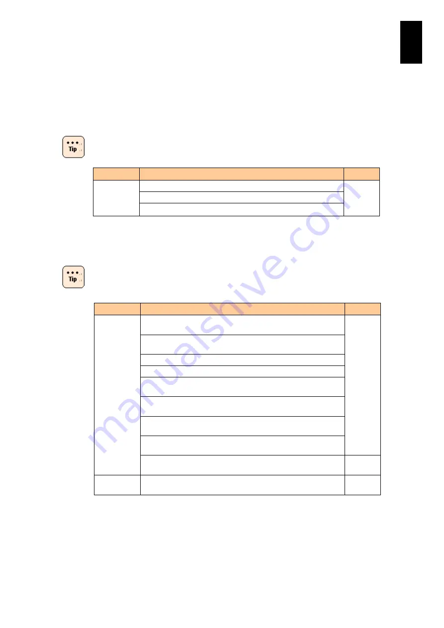
Component
Applicable product model
Note
Hard disk
GVX-UH21471X1/ equipped with the standard server blade
(*1)
GVX-UH21474X1 equipped with the standard server blade
GVX-UH23001X1 equipped with the standard server blade
*1 The designed service life is about two years if you use the component that is energized
for 24 hours a day and 30 days a month under the installation environment defined in
"Installation Environment"(Page.2). Should you use the component beyond the above
environmental conditions, the system may fail or suffer deteriorated service life.
No life time is set to hard disks described in the table below.
Maintenance service is available for five years from the
purchase date.
*
1
*1 Solid state drive (SSD) has features including excellent random access performance,
shock resistance, and low power consumption, but restrictions on writing amount.
Typical amount written in a server is expected to be around 50 GB/day. In the
environment with frequent writing, the amount may reach the upper limit.
*2 If you leave a dead SSD for a long time, the data on the SSD disappears. When SSD's
days are numbered, it sends a S.M.A.R.T. (Self-Monitoring Analysis and Reporting
Technology) error. Monitor errors in SSD using the Redundant Arrays of Independent
Disks (RAID) management utility. When a S.M.A.R.T. error is detected, replace the SSD
Component
Applicable product model
Note
Hard disk
GVX-UH26001X1/GV-UH26001X1-Y equipped with the standard
server blade
-
GVX-UH21473X1/GV-UH21473X1-Y equipped with the standard
server blade
GV-UH21471X1-Y equipped with the standard server blade
GV-UH23001X1-Y equipped with the standard server blade
GVX-UH21475X1/GV-UH21475X1-Y equipped with the standard
server blade
GVX-UH23003X1/GV-UH23003X1-Y equipped with the standard
server blade
GVX-UH26002X1/GV-UH26002X1-Y equipped with the standard
server blade
GVX-UH29001X1/GV-UH29001X1-Y equipped with the standard
server blade
GVX-UH24001X1/GV-UH24001X1-Y equipped with the standard
server blade
SSD *1 *2 *3 GVX-UH22001X1/GV-UH22001X1-Y equipped with the standard
server blade
-
Summary of Contents for Compute Blade 2000
Page 1: ...MK 99BDS2K001 16 Hitachi Compute Blade 2000 User s Guide ...
Page 42: ...xlii Precautions for Safe Use Rear View of A1 A2 Chassis ...
Page 43: ...xliii Precautions for Safe Use Rear View of A2 Chassis ...
Page 44: ...xliv Precautions for Safe Use Server Blade ...
Page 45: ...xlv Precautions for Safe Use I O Slot Expansion Unit ...
Page 46: ...xlvi Precautions for Safe Use I O Module ...
Page 47: ...xlvii Precautions for Safe Use AC Power Input Module ...
Page 51: ...li How to Use the Manuals This page is intentionally left blank ...
Page 61: ...10 1 Before Use ...
Page 64: ...13 2 How to Use the System Equipment Rear view of A1 chassis Rear view of A2 chassis ...
Page 93: ...42 2 How to Use the System Equipment ...
Page 123: ...72 3 Connecting the System Equipment and Powering On ...
Page 272: ...221 5 Server Blade Setup 3 Check Del and click Go The following screen appears 4 Click Yes ...
Page 345: ...294 5 Server Blade Setup 12 Click Next The following screen appears ...
Page 351: ...300 5 Server Blade Setup 3 Check Delete and click Go The following screen appears 4 Click Yes ...
Page 426: ...375 5 Server Blade Setup 3 Check Delete and click Go The following screen appears 4 Click Yes ...
Page 430: ...379 5 Server Blade Setup 3 Click Go Hotspare is set to the specified hard disk ...
Page 479: ...428 5 Server Blade Setup ...
Page 717: ...666 6 Management Module Settings Details of a physical partition ...
Page 722: ...671 6 Management Module Settings Server blade details view ...
Page 723: ...672 6 Management Module Settings ...
Page 732: ...681 6 Management Module Settings Management module details view ...
Page 745: ...694 6 Management Module Settings Optional Physical WWN list view ...
Page 748: ...697 6 Management Module Settings Optional Physical WWN initialization view ...
Page 751: ...700 6 Management Module Settings ...
Page 754: ...703 6 Management Module Settings Power status details view ...
Page 767: ...716 6 Management Module Settings ...
Page 768: ...717 6 Management Module Settings ...
Page 769: ...718 6 Management Module Settings ...
Page 814: ...763 6 Management Module Settings Power status trend view partition ...
Page 817: ...766 6 Management Module Settings Access log display view ...
Page 819: ...768 6 Management Module Settings WWN change log display view ...
Page 879: ...828 7 Configuring the LAN Switch Module Link aggregation adding editing screen ...
Page 899: ...848 8 Configuring the 10 Gb DCB Switch Module ...
Page 919: ...868 10 Configuring the Fibre Channel Switch Module ...
Page 1535: ...1484 12 Logical partitioning manager ...
Page 1877: ...1826 14 14 When You Need Help ...
Page 1925: ...16 Glossary ...


