background image

WERKSTATTHANDBUCH

WORKSHOPMANUAL

MANUEL D´ATELIER

MANUAL DE TALLER

MANUALE PER I´OFFICINA
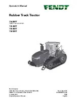
FAVORIT 900

916 

chassis no. 23/3001 and up

920 

chassis no. 23/3001 and up

924 

chassis no. 23/3001 and up

926 

chassis no. 23/3001 and up

Note:
If not noted otherwise, is the document valid for the North-America
version also (chassis no. 9xx/24/xxxx)

Ausgabe 12/2001 Edition

Xaver FENDT GmbH & CO.

Ein Unternehmen der AGCO-Corp.

Maschinen- und Schlepperfabrik, Marktoberdorf / Bayern Germany
Postfachadresse:

 D-87609 Marktoberdorf, Postfach 1155

Telefon (0 83 42) 77-0      Telefax (0 83 42) 77-2 22 (Kundendienst)

Bestell-Nr. / order no. / no. De comande / no. Die ordinazione

X 990.005.040.010 en

2711C - en

Summary of Contents for FAVORIT 900

Page 1: ...f not noted otherwise is the document valid for the North America version also chassis no 9xx 24 xxxx Ausgabe 12 2001 Edition Xaver FENDT GmbH CO Ein Unternehmen der AGCO Corp Maschinen und Schlepperf...

Page 2: ...Emergency control 1100 Clutch actuation system 1150 Cardan brake 1170 ML range control 1200 Front PTO 1220 Live PTO 1320 Front wheel drive 1430 Hydrodamp 1432 Hydraulic pump 1470 Transmission lubricat...

Page 3: ...eering cylinder 3170 Frame 3180 Cardan shaft 3190 Diff lock actuation system 4000 Steering 4070 Steering wheel 4090 Hydr steering assembly 5000 Vehicle body 5010 Body 5030 Driver s seat 5050 Hitch 516...

Page 4: ...rame 8915 Hydr implement actuation system 8955 3rd hydr circuit 8958 Multi coupling 8970 Pipes 8990 Lift cylinder 9000 Electrics 9010 Generator 9015 Starter inhibitor 9040 Fuses 9050 Battery system 90...

Page 5: ...ipment 9605 Hydr connections 9610 Central control block ZSB 9620 Valve fitting 9666 External hydraulic supply 9690 Valve supplement 9700 Electronics 9710 Instrument panel 9715 Vario terminal 9717 LBS...

Page 6: ...ivided into various registers which are labelled with a register letter These are as follows This documentation comprises a large number of self contained individual documents worksheets These documen...

Page 7: ...l assemblies are paginated sequentially starting at page 1 Text module The document code does not have to be sequential i e gaps may occur The docu no is not the page number in the documentation The p...

Page 8: ...me that the Workshop Manual was written Technical refinement of the product and expansions in terms of different models may require different work procedures which can be carried out without major dif...

Page 9: ...nually before any repair is carried out or anything is released or opened in this area Note The Lock suspension lower suspension command has no effect Steps PM Picturemodule PM Picturemodule Text modu...

Page 10: ...de 13 Special hypoid transmission oil 85 W 140 to API GL 5 After 500 op hrs then every 2 years or 2000 op hrs Hydraulics STOU SAE 10W 30 10W 40 15W 30 After 1000 op hrs Quantity for max filling 70 Als...

Page 11: ...cants sealants and bonding agents High pressure grease for long term lubrication e g for splined shaft profiles X 902 002 472 long life grease Grease for lubricating sealing lips of shaft seals Multi...

Page 12: ...1 Capitel Docu No Index Date Version Page Tightening torques for screws bolts in Nm kpm Text module Coefficient of friction tot 0 14 for nuts and bolts without aftertreatment and for phosphated nuts...

Page 13: ...tel Docu No Index Date Version Page Tractor diagnostics with terminal A008 PM Picturemodule PM Picturemodule PM Picturemodule PMTAB_Picture Ignition ON Press F5 to switch to second main menu level PMT...

Page 14: ...gh is the transmission discharge temperature for various tasks Checking setpoint engine speed PMTAB_Picture Diagnostics menu is displayed High pressure Transm ission Sens or B008 indicates oil pressur...

Page 15: ...940 4940 Overall width mm 2550 2550 Overall height incl cab mm 3095 3095 Ground clearance mm 605 605 Wheelbase mm 2840 2840 Flange centre distance front mm 1892 1892 Flange centre distance rear mm 189...

Page 16: ...ques 4000 Nm Hydraulics Working pressure bar 200 200 Hydraulic pump l 112 112 Available hydr oil at max capacity l 50 50 Rear power lift Three point Cat 2 3 Cat 2 3 Control EPC EPC Max lift capacity k...

Page 17: ...0 4940 Overall width mm 2580 2640 Overall height incl cab mm 3110 3110 Ground clearance mm 605 605 Wheelbase mm 2840 2840 Flange centre distance front mm 1892 1892 Flange centre distance rear mm 1890...

Page 18: ...es 4000 Nm Hydraulics Working pressure bar 200 200 Hydraulic pump l 117 117 Available hydr oil at max capacity l 50 50 Rear power lift Three point Cat 2 3 Cat 2 3 Control EPC EPC Max lift capacity kN...

Page 19: ...A002 Transmission control module Bus Failure no functions available no display Voltage supply CAN Bus on fuse board A013 fuses F040 F041 0 0 15 A001 A002 AWD Differential Lock acivation Bus Failure no...

Page 20: ...temperature sensor Sensor failure wiring failure no monitoring Electrical diagram Dashpanel 0 1 57 B006 Sensor intercooler temperature Sensor fault wiring fault No monitoring Circuit diagram Instrumen...

Page 21: ...ansmission BUS Comfort BUS 1 1 A0 A021 EDC control module EDC control module A021 cannot be identified EOL Programming error According to failure importance Engine torque will be reduced to Fav 916 to...

Page 22: ...Motorsteuerung 1 2 23 A002 EST control module CAN Message failure from EST control module A002 EDC control module Chapter 2000 Reg B EDC Failure Electric diagram Transmission BUS EDC Control Module 1...

Page 23: ...control module Transmission bus circuit diagrams 1 2 38 A021 EDC Control Module Function failure EDC Control Module Engine Stop restricted power Chapter 2000 Reg B EDC Failure Electric diagram EDC Co...

Page 24: ...via Injected volume 0 fehlerhaft se Chapter 2710 Reg A Engine Stop Restricted power Chapter 2000 Reg B EDC Failure Electric diagram EDC Control 1 2 96 A021 EDC Control Module Monitoring unit Failure E...

Page 25: ...Injection pump Failure identified during auto diagnostic restricted Power Chapter 2000 Reg B EDC Failure 1 2 B3 A020 Pump Control Injection pump Supply failure Pumpe Control Chapter 2710 Reg A Engine...

Page 26: ...ns idle 720 Rpm Chapter 2000 Reg B EDC Failure Electric diagram EDC Control 1 2 C5 A021 A020 EDC Control Module Pump Control Injection pump Failure durin Engine Stop via Solenoid valve Chapter 2710 Re...

Page 27: ...A021 A002 EDC Control Module EST Comfort Module Communication failure during CAN Message between EDC Control Module and EST Contol Module Chapter 2000 Reg B EDC Failure Electric diagram EDC Control Tr...

Page 28: ...ilure Functions switched off keypad digital analogue input LED actuation Fit new control console 3 1 06 A004 Side Console 8 5 Volt Failure Functions switched off keypad digital analogue input LED actu...

Page 29: ...olt A013 fuse 13 4 1 21 S045 Position sensor Reversed Operating Controls Signal failure 4 1 23 A003 Joystick Cruise Control Activate Signal failure Only Auxilliary Operation Electric diagram Transmiss...

Page 30: ...ary Operation Electric diagram Transmisson Control TRANSMISSION 4 1 30 Contact Auxilliary Operation Hatch Open Closed Signal failure Only Auxilliary Operation valid only for FAV900 with telescopic han...

Page 31: ...17 Contact Transmission Oil Filter contaminated Filter contaminated no further indication of contamination Electrical diagram Transmission Control Only Twin EST Module version TRANSMISSION TRANSMISSIO...

Page 32: ...ON 4 1 64 Y004 Solenoid valve neutral turboclutch PWM Supply failure Electrical diagram Transmission Control TRANSMISSION 4 1 65 Y006 Solenoid valve exhaust brake Supply failure TRANSMISSION only for...

Page 33: ...Control Module FAV900 EDC Calibration Code 4011 4 1 7F A003 Memorizing key Selected engine speed Signal failure Electric diagram EDC Control Module FAV900 with EDC 4 1 81 B010 B011 Speed sensor motor...

Page 34: ...available Only for FAV700 900 twin e box version 4 1 93 A001 A002 Brake pedal left data communication Data communication fault Automatic cruise control not available Only for FAV700 900 twin e box ver...

Page 35: ...cation 4 1 B1 Y001 Y002 Speed range control Illogical speed range operation fatal error Continuation in emergency mode possible 4 1 B2 A002 ECU enhanced control Fault in EPROM programming range contro...

Page 36: ...s Continuation in emergency mode possible TRANSMISSION calibration code 4007 4 1 EF Turboclutch characteristic No calibration or drifted values Continuation in emergency mode possible TRANSMISSION TUR...

Page 37: ...Signal fault Automatic differential lock not available 4WD Diff Lock circuit diagram DIFFERENTIAL LOCK ENHANCED CONTROL 5 1 55 S005 Right brake pedal solenoid switch Signal fault Automatic differentia...

Page 38: ...tinuation without suspension possible SUSPENSION ENHANCED DIAGNOSTIC SYSTEM only with single e box version Fault in bus signal from A004 to A002 CAN enhanced controls bus circuit diagram 5 1 66 Y012 V...

Page 39: ...initially 2 Valve flow is automatically reduced 3 If pressure operated switch remains open for 2 more seconds then fault code and locking of valves no supply to control pressure valve Y032 4 If press...

Page 40: ...pump flow monitor Switch fault does not close is still open without oil flow test sequence 2 4 5 1V No monitoring from 09 2000 or from A002 Vario V090 software the fault will only be stored if the tem...

Page 41: ...or FAV 700 5 1 B0 A002 ECU enhanced control CAN bus communication restricted EOL reprogramming necessary 5 1 FF A002 ECU enhanced control Internal fault RAM EEPROM 6 1 01 A004 Rear PTO ON OFF key in c...

Page 42: ...gaged by pressing emergency key in cab for 5 seconds COMFORT REAR PTO 6 1 11 A004 Rear PTO automatic mode key Signal fault PTO disengages automatic mode OFF Circuit diagram PTO s Fav700 COMFORT REAR P...

Page 43: ...ctuation fault PTO cannot be engaged Circuit diagram PTO s Only for single e box version Not for Fav 900 COMFORT REAR PTO 6 1 1C Y027 Rear PTO speed 1000 solenoid valve Actuation fault PTO cannot be e...

Page 44: ...ch speed deviates by more than 20 from engine speed Clutch is slipping Activating speeds remains possible press Engage PTO key for more than 5 seconds emergency mode Circuit diagram PTO s Only for sin...

Page 45: ...gram PTO s Only for Fav 700 single e box version COMFORT REAR PTO 6 1 55 A004 NEUTRAL speed selection key has been pressed for more than 30 seconds mechanical or electrical fault in key All speeds can...

Page 46: ...028 wrongly wired or seized Mechanical fault in speed selector Signal fault at Hall effect sensor B020 B021 Electric speed selection remains possible press Engage PTO key for more than 5 seconds emerg...

Page 47: ...ront PTO brake external pushbutton Signal fault Circuit diagram PTO s Fav900 COMFORT FRONT PTO 7 1 03 Y034 Release brake front PTO solenoid valve Actuation fault Circuit diagram PTO s 7 1 04 Y011 PTO...

Page 48: ...MFORT FRONT PTO 7 1 42 S041 Release brake key Plausibility error key has been pressed for more than 30 seconds Only for Fav 900 Single e box version COMFORT FRONT PTO 7 1 4A A004 Active key Plausibili...

Page 49: ...EAR EPC EXTERNAL PUSHBUTTONS 8 3 15 S030 Lower rear power lift external pushbotton cab left rear Signal line fault Control locked Electrohydraulic power lift control circuit diagram REAR EPC EXTERNAL...

Page 50: ...ETPOINT POSITION SENSOR 8 3 24 Rear power lift lift height limit rotary control Signal fault Control locked Only for FAV900 with twin control modules 8 3 26 External position sensor for rear power lif...

Page 51: ...power lift control circuit diagram Only for FAV900 with twin control modules 8 3 38 Rear power lift pressure sensor Signal fault pressure sensor fault Control is continued Electrohydraulic power lift...

Page 52: ...04 A005 8 3 50 B031 draft sensing pin Rear EPC right draft sensing pin Draft sensing pin is overloaded as a result of twisting lift in upper range 90 100 lift height due to too tight setting Fault cod...

Page 53: ...l position FRONT POWER LIFT 9 1 53 Spool valve fault Supply voltage 18 volts Valve moves into neutral position FRONT POWER LIFT 9 1 54 Spool valve fault Main Piston travel too short due to drop of con...

Page 54: ...ced control EEPROM fault while storing Set values enhanced controls are not stored 9 1 A1 A002 ECU enhanced control EEPROM fault while loading Set values enhanced controls cannot be read 9 1 B0 B040 P...

Page 55: ...on Key fault No function Circuit diagram Spool valves 2 FRONT POWER LIFT 9 1 D1 S022 Lower front power lift external pushbutton Key fault No function Circuit diagram Spool valves 2 FRONT POWER LIFT A...

Page 56: ...controlled functions can occur DANGER SPOOL VALVES 1 4 A 1 19 Spool valve fault valve 1 Main piston cannot return to neutral position when switched on because of oil contamination SPOOL VALVES 1 4 A 1...

Page 57: ...position A 1 24 Spool valve fault valve 2 Main piston travel too short due to drop of control pressure below 22 bar Valve moves into neutral position SPOOL VALVES 1 4 Hydraulic oil temperature to low...

Page 58: ...ing position has been set manually No consequences SPOOL VALVES 1 4 A 1 2F Spool valve fault valve 2 Setpoint message is missing or not plausible Valve moves into neutral position SPOOL VALVES 1 4 set...

Page 59: ...e 3 Internal position sensor fault Valve moves into neutral position SPOOL VALVES 1 4 A 1 38 Spool valve fault valve 3 Main piston cannot return into neutral position because of oil contamination Unde...

Page 60: ...ts Valve moves into neutral position A 1 43 Spool valve fault valve 4 Supply voltage 18 volts Valve moves into neutral position A 1 44 Spool valve fault valve 4 Main piston travel too short due to dro...

Page 61: ...ition SPOOL VALVES 1 4 A 1 4C Spool valve fault valve 4 Floating position has been set manually No consequences SPOOL VALVES 1 4 A 1 4F Spool valve fault valve 4 Setpoint message is missing or not pla...

Page 62: ...Circuit diagram Spool valves 1 SPOOL VALVES OPERATION A 1 B4 A003 Crossgate lever Zero position signals of X and Y axes are not identical to the Rest position signal plausibility check Valves cannot b...

Page 63: ...om hydraulic connection to front power lift Circuit diagram Spool valves 1 A 1 D6 S021 External Lift pushbutton No valve operation available Circuit diagram Spool valves 1 STANDARD FRONT POWER LIFT or...

Page 64: ...witching from EPC to DA and vice versa impossible A 1 E2 Pilot valve fault Switching from EPC to DA and vice versa impossible A 1 E3 Shutoff valve fault Switching from EPC to DA and vice versa impossi...

Page 65: ...upply fault No oil heating during start up process for LS pump at low ambient temperature Circuit diagram Suspension SPOOL VALVES OVERVIEW OF OPERATION VALVES 1 4 A 1 F1 A013 Fuseboard Overall 8 5 V p...

Page 66: ...O A B C D E F G H J K L X Front axle load too high X Raise valve Y014 Fault in coil cartridge X Lower valve Y013 Fault in coil cartridge X Raise nozzle Bl 3 Blocked Visual inspection blow through if n...

Page 67: ...ise white chromated Lo wer yellow chroma ted X X Position sensor B003 Fault in mech con nection X Suspension characteristic incorrect Faulty diaphragm in accumulator i e reduction in nitrogen pre tens...

Page 68: ...k of working pressure only when steering Steering side leak in shuttle valve WLS1 Blow through replace O Steering pressure relief valve DBV L too low X Priority valve PVL not operating Piston not func...

Page 69: ...fficient residual oil volume in tank Check O Visco fan does not kick in Check X Enginespeedtoolow X X O Pressure overlap overpressure effect at Working pressure of 200 bar increased without authority...

Page 70: ...re drop in shuttle valve WLS1 X Air in LS duct See also Operating with ext control blocks X Blockage e g dirt be fore a shuttle valve X LS pump entraining air Tank empty Check operation of level senso...

Page 71: ...tor Check O Insufficient residual oil volume in tank Check O Visco fan does not kick in Check X Enginespeedtoolow X LS pump working constantly against pressure Implement cannot reach setpoint Check X...

Page 72: ...ause Action if neces sary see O A B C D E F G H J K L X Lack of cooling Contaminated radiator Check O Insufficient residual oil volume in tank Check O Visco fan does not kick in Check X Enginespeedtoo...

Page 73: ...8 20 22 3 18 19 20 22 3 19 20 21 23 A006 Keypad on front dashboard X035 21 21 21 22 A007 Instrument panel X100 X101 X102 3 5 7 8 18 19 20 21 22 5 7 8 18 20 21 22 25 3 5 7 8 18 19 20 21 22 24 26 3 5 7...

Page 74: ...re transducer X168 21 21 21 22 B020 Rear PTO Hall effect speed sensor X169 29 28 29 30 B021 Rear PTO Hall effect speed sensor after clutch X170 29 28 29 30 B022 Kickout pressure operated switch X171 2...

Page 75: ...13 E012 Work light in roof rear left X388 X389 X390 12 12 12 13 E013 Work light in roof front right X291 11 11 11 12 E014 Work light in roof front left X294 11 11 11 12 E015 Work light front on right...

Page 76: ...005 Horn X998 X999 7 7 7 8 H006 Beeper 21 21 21 22 H010 Telltale 2nd alternator X210 5 DIN Designation Con nec tor Farmer 400 Fav 700 twin e box Fav 700 single e box Fav 900 K001 Ub 15 relay X070 2 2...

Page 77: ...switch relay USA K033 Fuel preheater relay 5 DIN Designation Con nec tor Farmer 400 Fav 700 twin e box Fav 700 single e box Fav 900 M001 Starter X061 X063 2 4 2 4 2 4 4 M002 Front wiper motor X347 4 1...

Page 78: ...S019 PTO ON key rear left X229 29 28 29 30 S020 PTO ON key rear right X230 29 28 29 30 S021 Raise front power lift ext pushbutton X231 24 24 25 S022 Lower front power lift ext pushbutton X232 24 24 2...

Page 79: ...signation Con nec tor Farmer 400 Fav 700 twin e box Fav 700 single e box Fav 900 Y001 Increased quantity solenoid valve 4 Y002 Speed range 1 solenoid valve X315 26 25 26 27 Y003 Speed range 2 solenoid...

Page 80: ...clutch X342 14 14 14 Y025 Cold start aid solenoid valve X092 5 5 5 5 Y026 Rear PTO stage 1 solenoid valve X360 29 30 Y027 Rear PTO stage 2 solenoid valve X361 29 30 Y028 Rear PTO stage 3 solenoid valv...

Page 81: ...cable loom Connecting auxiliary implements note cross sections of cables Text module Note Cable nos are printed on cable sheaths PM Picturemodule PM Picturemodule PM Picturemodule PMTAB_Picture Cable...

Page 82: ...sion Page Electrical electronic components A PM Picturemodule PM Picturemodule PM Picturemodule PM Picturemodule PMTAB_Picture A002 ECU enhanced control A005 ECU lift assembly In cab on right mudguard...

Page 83: ...ctrical electronic components A PM Picturemodule PM Picturemodule PM Picturemodule PM Picturemodule PMTAB_Picture A007 Display unit At top of steering column PMTAB_Picture A008 Vario terminal On right...

Page 84: ...al electronic components A PM Picturemodule PM Picturemodule PM Picturemodule PM Picturemodule PMTAB_Picture A011 Sensor radar On right below cab Remove rear wheel Remove panels on right PMTAB_Picture...

Page 85: ...D Component Location Fav 900 chassis number 23 3001 and up 08 2000 0000 000028 D a 4 4 Capitel Docu No Index Date Version Page Electrical electronic components A PM Picturemodule PMTAB_Picture A021 EC...

Page 86: ...ule PM Picturemodule PMTAB_Picture B001 Sensor steering angle 1 B024 Sensor steering angle 2 On steering knuckle of right front axle Remove cover 20 B001 top and B024 bottom are labelled A and D PMTAB...

Page 87: ...Picturemodule PMTAB_Picture B005 Sensor engine temperature Engine compartment on water pipe fan side Open left side of bonnet PMTAB_Picture B006 Sensor intercooler temperature Engine compartment on in...

Page 88: ...odule PM Picturemodule PM Picturemodule PMTAB_Picture B010 Sensor engine 1 B011 Sensor engine 2 Top left rear on engine PMTAB_Picture B012 Sensor engine oil pressure On left of engine on oil filter ho...

Page 89: ...uremodule PMTAB_Picture B015 Sensor bevel pinion At bottom right of transmission Unscrew right rear wheel and panel PMTAB_Picture B016 Sensor range sensor On right behind fuel tank Remove fuel tank on...

Page 90: ...icturemodule PM Picturemodule PMTAB_Picture B020 Sensor PTO 1 B021 Sensor PTO 2 At rear above PTO stub shaft Remove cover panel PMTAB_Picture B022 Sensor kickout At right entrance step on left connect...

Page 91: ...remodule PM Picturemodule PM Picturemodule PMTAB_Picture B027 Sensor water temperature Engine compartment on water pipe flywheel side Open left side of bonnet PMTAB_Picture B028 Sensor boost pressure...

Page 92: ...ion Page Electrical electronic components B PM Picturemodule PM Picturemodule PM Picturemodule PM Picturemodule PMTAB_Picture B031 Sensor draft sensing pin right Cross beam bearing PMTAB_Picture B032...

Page 93: ...dule PM Picturemodule PMTAB_Picture B038 Sensor accelerator Cab under steering column Remove steering column cover at bottom left PMTAB_Picture B040 Sensor front power lift position On right bottom li...

Page 94: ...D Component Location Fav 900 chassis number 23 3001 and up 01 08 2000 0000 000029 D a 9 9 Capitel Docu No Index Date Version Page Electrical electronic components B PM Picturemodule PMTAB_Picture B05...

Page 95: ...cator sidelight front right E006 Indicator sidelight front left Tractor seen from front PMTAB_Picture E007 Tail light rear right E008 Tail light rear left E009 Licence plate light right E010 Licence p...

Page 96: ...electronic components E PM Picturemodule PM Picturemodule PM Picturemodule PM Picturemodule PMTAB_Picture E019 UB cab lighting At top in cab roofliner PMTAB_Picture E020 EPC lighting At top right in c...

Page 97: ...Index Date Version Page Electrical electronic components E PM Picturemodule PM Picturemodule PM Picturemodule PMTAB_Picture E028 Indicator right USA front E029 Indicator left USA front Tractor seen f...

Page 98: ...mponents G PM Picturemodule PM Picturemodule PM Picturemodule PM Picturemodule PMTAB_Picture G001 Battery In central part of tractor on left below fuel tank Open battery cover PMTAB_Picture G002 Alter...

Page 99: ...l Docu No Index Date Version Page Electrical electronic components H PM Picturemodule PM Picturemodule PM Picturemodule PMTAB_Picture H005 Horn Bottom right in centre of tractor Opening the front sect...

Page 100: ...56A K005 Relay 56B K007 Relay brake K008 Relay starter inhibitor K009 Relay windscreen wiper K010 Relay direction indicator controller K013 Relay 3rd hydraulic circuit K014 Relay exhaust brake K015 R...

Page 101: ...ponent Location Fav 900 chassis number 23 3001 and up 08 2000 0000 000031 D a 2 2 Capitel Docu No Index Date Version Page Electrical electronic components K PM Picturemodule PMTAB_Picture K033 Relay f...

Page 102: ...dule PM Picturemodule PM Picturemodule PM Picturemodule PMTAB_Picture M002 Wiper motor front In windscreen Unscrew cover PMTAB_Picture M003 Wiper pump front M005 Wiper pump rear In windscreen washer b...

Page 103: ...e Version Page Electrical electronic components M PM Picturemodule PM Picturemodule PM Picturemodule PMTAB_Picture M008 Motor heater fan In front of cab Remove cover from bonnet filter and heater PMTA...

Page 104: ...ponents R D Component Location Fav 900 chassis number 23 3001 and up 24 9 2001 0000 000040 D a 1 1 Capitel Docu No Index Date Version Page Electrical electronic components R PM Picturemodule PMTAB_Pic...

Page 105: ...ectronic components S PM Picturemodule PM Picturemodule PM Picturemodule PM Picturemodule PMTAB_Picture S001 Switch control stalk On left of steering wheel PMTAB_Picture S002 Switch ignition On right...

Page 106: ...uremodule PM Picturemodule PMTAB_Picture S006 Switch left brake At top on brake pedals Remove panel PMTAB_Picture S008 Switch front working lights S009 Switch rear working lights S010 Switch rear wipe...

Page 107: ...PM Picturemodule PM Picturemodule PM Picturemodule PM Picturemodule PMTAB_Picture S014 Switch rapid reversing To left of steering wheel PMTAB_Picture S015 Switch handbrake At rear on left brake cylin...

Page 108: ...e S021 Switch raise front power lift S022 Switch lower front power lift Front left PMTAB_Picture S023 Switch lock front power lift On right entrance step by stopcock AVF Remove cover panel PMTAB_Pictu...

Page 109: ...Picture S026 Switch flow monitor By auxiliary pump in space between transmission and engine in frame Remove right side of bonnet PMTAB_Picture S027 Switch raise rear power lift right S028 Switch lower...

Page 110: ...dule PM Picturemodule PM Picturemodule PM Picturemodule PMTAB_Picture S033 Switch heater control On left of steering column PMTAB_Picture S034 Switch coolant level Expansion tank at rear of engine com...

Page 111: ...ion Page Electrical electronic components S PM Picturemodule PM Picturemodule PM Picturemodule PM Picturemodule PMTAB_Picture S037 Switch fan Top right in cab PMTAB_Picture S044 Switch air conditionin...

Page 112: ...08 2000 0000 000030 D a 8 8 Capitel Docu No Index Date Version Page Electrical electronic components S PM Picturemodule PM Picturemodule PMTAB_Picture S048 Switch EPC DA switchover Rear of tractor abo...

Page 113: ...V D Component Location Fav 900 chassis number 23 3001 and up 08 2000 0000 000032 D a 1 1 Capitel Docu No Index Date Version Page Electrical electronic components V PM Picturemodule PMTAB_Picture V003...

Page 114: ...onents X PM Picturemodule PM Picturemodule PM Picturemodule PM Picturemodule PMTAB_Picture X003 Load contact chassis cab base Left side of tractor Remove panel PMTAB_Picture X007 Cable coupler impleme...

Page 115: ...AB_Picture X010 External start terminal plus On left of battery frame Remove cover panel and protective cap from K018 relay battery switch PMTAB_Picture X014 Cable coupler cab cab base In cab on right...

Page 116: ...coupler 3rd hydraulic circuit socket Left side of tractor in region of starter motor Open left side of bonnet PMTAB_Picture X025 LBS prewiring X026 Cable coupler communication box In cab on right mudg...

Page 117: ...M Picturemodule PMTAB_Picture X029 Cable coupler cab cab base In cab on right mudguard at front Remove hatch cover from control console at front PMTAB_Picture X032 Connector A003 joystick At bottom ri...

Page 118: ...Picturemodule PMTAB_Picture X040 Cable coupler cab base engine X041 Cable coupler cab base engine X042 Cable coupler cab base engine Left side of tractor Remove panels PMTAB_Picture X043 Cable couplte...

Page 119: ...PM Picturemodule PM Picturemodule PM Picturemodule PMTAB_Picture X050 Fuse holder 1 compl X051 Fuse holder 2 compl At right rear in cab Remove cover PMTAB_Picture X052 Chassis plus terninal On left s...

Page 120: ...oupler S012 switch starter inhibitor At top of steering column Remove instrument panel PMTAB_Picture X103 Earthing point A002 ECU enhanced control In cab on right mudguard Remove panel PMTAB_Picture X...

Page 121: ...turemodule PM Picturemodule PM Picturemodule PM Picturemodule PMTAB_Picture X118 Earthing point A004 ECU control console In cab on right mudguard Remove panel PMTAB_Picture X150 Connector B001 B024 se...

Page 122: ...amp 2 generator At top of steering column Remove hatch cover at top of steering column then remove instrument panel PMTAB_Picture X215 Cable coupler S001 switch control stalk At rear of steering colum...

Page 123: ...Picture X236 Cable coupler S026 switch flow monitor By auxiliary pump in space between transmission and engine in frame Open right side of bonnet PMTAB_Picture X245 Cable coupler S001 switch control s...

Page 124: ...inal E029 heated rear window At rear wiper motor Remove panel PMTAB_Picture X261 Radio earth X262 UB radio Not assigned Radio aerial A015 Radio not shown At top right in cab Remove radio housing blank...

Page 125: ...dule PMTAB_Picture X277 Lighting wide load left earth X278 Lighting wide load left UB At top right in cab Remove radio housing blanking plate PMTAB_Picture X281 Connector air conditioning Note Shown w...

Page 126: ...emodule PM Picturemodule PM Picturemodule PMTAB_Picture X294 E014 work lights in roof front left Top front in roof Pivot bracket for work lights in roof upwards PMTAB_Picture X297 Connector M002 front...

Page 127: ...hting wide load right UB X314 Lighting wide load right earth Front left in roof Remove cab roof PMTAB_Picture X337 Terminal E024 right heated mirror X338 Terminal E024 right heated mirror Top front in...

Page 128: ...r On front wiper motor Remove panel PMTAB_Picture X367 Cable coupler E018 left work lights Note Photo shows left connector X366 cable coupler E017 right work lights is analogous Remove indicator brake...

Page 129: ...PM Picturemodule PM Picturemodule PMTAB_Picture X405 Connector steering angle sensors Right front axle Unscrew cover from axle housing PMTAB_Picture X406 UB not currently assigned Right side of tracto...

Page 130: ...module PM Picturemodule PM Picturemodule PMTAB_Picture X415 Connector A pillar Front right in roof Remove cab roof PMTAB_Picture X416 Connector A pillar Front left in roof Remove cab roof PMTAB_Pictur...

Page 131: ...B_Picture X442 Connector bonnet front At top above radiator Opening the front section PMTAB_Picture X451 Cable lug plus terminal chassis On left side of tractor in flywheel housing Note Shown with fue...

Page 132: ...al cab base On left side of tractor in flywheel housing Note Shown with fuel tank removed for greater clarity PMTAB_Picture X462 Earthing point cab base In cab at front right in front of control conso...

Page 133: ...turemodule PMTAB_Picture X497 Connector LBS prewiring front In cab on right mudguard at front Remove hatch cover on control console and mudguard panel at front PMTAB_Picture X499 UB30 LBS 40 amps Righ...

Page 134: ...e left On left side of tractor on flywheel housing Open left side of bonnet PMTAB_Picture X520 Earthing point engine right X521 Earthing point engine right On right side of tractor on flywheel housing...

Page 135: ..._Picture X550 Earthing point cab base In cab at front right in front of control console Unscrew hatch cover PMTAB_Picture X551 Earthing point cab base X552 Earthing point cab base X553 Earthing point...

Page 136: ...point transmission Rear of tractor right axle tube PMTAB_Picture X591 Connector UB30LBSimplementsocket On left side of tractor in flywheel housing Note Shown with fuel tank removed for greater clarity...

Page 137: ...re X608 Connector UB15 X609 Connector UB58 lighting In cab on right mudguard Remove panel PMTAB_Picture X610 Connector E007 right indicator X611 Connector E008 left indicator In cab at front right in...

Page 138: ...cture X617 Connector G bus CAN low X618 Connector G bus CAN high In cab on right mudguard Remove panel PMTAB_Picture X619 Connector earth electronics 3 X620 Connector earth electronics 2 X621 Connecto...

Page 139: ...cal electronic components X PM Picturemodule PM Picturemodule PM Picturemodule PMTAB_Picture X629 Connector UB30 A002 ECU enhanced control In cab on right mudguard Remove panel PMTAB_Picture X630 Conn...

Page 140: ...X632 Connector S027 switch raise rear power lift right Connector S028 switch lower rear power lift right Connector S029 switch raise rear power lift left Connector S030 switch lower rear power lift l...

Page 141: ...it Top front of steering column Remove A007 display unit PMTAB_Picture X637 Connector UB 15 A007 display unit At top of steering column Remove instrument panel PMTAB_Picture X638 Connector earth S025...

Page 142: ...Picturemodule PMTAB_Picture X643 Connector earth A007 display unit At top of steering column Remove instrument panel PMTAB_Picture X644 Connector UB 58 at front S002 switch ignition Bottom left in foo...

Page 143: ...X661 Connector earth electronics 4 In cab at front right in front of control console Unscrew hatch cover PMTAB_Picture X662 Connector G bus CAN low A021 ECU EDC Y015 Y016 valves A009 actuator unit X66...

Page 144: ...Connector earth Y021 Y022 valve raise lower suspension Cab right entrance step Remove footplate PMTAB_Picture X676 Connector earth B031 B032 sensor draft sensing pin X677 Connector UB B031 B032 sensor...

Page 145: ...le PM Picturemodule PMTAB_Picture X684 Connector LBS earth X685 Connector UB 30 251 Right rear mudguard Remove panels PMTAB_Picture X686 Connector LBS Can low X687 Connector LBS Can high X688 Connecto...

Page 146: ...cturemodule PM Picturemodule PM Picturemodule PMTAB_Picture X692 Connector UB 30 EDC control unit In cab on right mudguard Remove panels PMTAB_Picture X698 Connector earth A007 display unit Cab left s...

Page 147: ...nector earth sensor system 2 A004 ECU control console In cab at front right in front of control console Unscrew hatch cover PMTAB_Picture X745 Connector transmission sensor system to A004 ECU control...

Page 148: ...ule PMTAB_Picture Y002 Valve speed range 1 Y003 Valve speed range 2 Behind rear right wheel on valve unit Unscrew rear right wheel and panel PMTAB_Picture Y004 Valve transmission neutral turboclutch v...

Page 149: ...0 Valve diff lock On rear axle housing Raise cab at rear PMTAB_Picture Y011 Valve front PTO On front PTO gearbox at left Unscrew cover panel PMTAB_Picture Y012 MVL Valve charge suspension Charge valve...

Page 150: ...er PMTAB_Picture Y015 Valve 1 Control valve SB 23 LS EHS 1st control valve on underside of central control block Note EPC control valve is located between Y015 and Y016 Unscrew right step Pull right a...

Page 151: ...system At rear right above axle drive PMTAB_Picture Y025 Valve cold start aid At front on intake pipe Open left side of bonnet PMTAB_Picture Y026 Valve rear PTO speed 1 Y027 Valve rear PTO speed 2 On...

Page 152: ...a 5 5 Capitel Docu No Index Date Version Page Electrical electronic components Y PM Picturemodule PM Picturemodule PMTAB_Picture Y033 MVV Valve flush Opens flow from P via aperture 5 to tank In end pl...

Page 153: ...Control valves SB 23 EHS Relevant control valve for front power lift or for connections depending on tractor s equipment level 1 1 1 Valve 1 2 2 Valve 1 3 3 Valve 1 4 4 Control valve 1 5 5 Control va...

Page 154: ...onnection for hydraulic trailer brake valve Rear of tractor PMTAB_Picture ASP1 Accumulator no 1 with 1 4 l capacity 50 bar ASP2 Accumulator no 2 with 0 75 l capacity 50 bar Nitrogen diaphragm accumula...

Page 155: ...PC DA multiway valve Rear of tractor above rear connections Remove cover panel PMTAB_Picture AV5 Front power lift EPC DA multiway valve On right side of tractor underneath central control block Open c...

Page 156: ...omponents PM Picturemodule PM Picturemodule PM Picturemodule PM Picturemodule PMTAB_Picture Connection B Lower suspension Right side of ZSB PMTAB_Picture B on ABV Hydr pipe for hydraulic trailer brake...

Page 157: ...dule PM Picturemodule PM Picturemodule PMTAB_Picture BL5 Aperture no 5 d 1 5mm oil preheater In end plate PMTAB_Picture BL6 Aperture no 6 d 0 9mm in LS system BL7 Aperture no 7 d 0 8mm to increase con...

Page 158: ...ety valve for LS pump Note Not used for setting working pressure On top of ZSB PMTAB_Picture DBV HPS 250 bar pressure relief valve Safety and pressure relief valve for suspension DBV L 180 bar pressur...

Page 159: ...ine on auxiliary pump Raise side of bonnet PMTAB_Picture EF Hyd tank filler neck cover On right side of tractor in front of cab Raise side of bonnet PMTAB_Picture Lift rear EPC Lift solenoid valve Rea...

Page 160: ...icturemodule PM Picturemodule PMTAB_Picture FP Prefilter Sintered metal filter in P duct upstream of control pressure valve Y032 MVSt in end plate EP On right at entrance step lowest end plate with in...

Page 161: ...le PM Picturemodule PM Picturemodule PM Picturemodule PMTAB_Picture K Vorl Auxiliary pump PL cooler K tank Right side of ZSB PMTAB_Picture L on LE Steering unit for steering cylinder steering to right...

Page 162: ...Picturemodule PM Picturemodule PM Picturemodule PM Picturemodule PMTAB_Picture LS on LE Control line LS from steering unit to central control block ZSB In steering column Remove steering column panel...

Page 163: ...pressure for steering in need scenario or for hydraulic trailer brake At right entrance step on top of central control block PMTAB_Picture M3 Pressure measuring point no 3 LS pump readings min standby...

Page 164: ...L Solenoid valve Charge valve for suspension and oil preheater Fav 700 and Fav 900 At right entrance step top of central control block ZSB in bore 2011 of ZSB PMTAB_Picture MVSt Solenoid valve neutral...

Page 165: ...dule PM Picturemodule PM Picturemodule PMTAB_Picture P LS pump output to control valves On bottom of ZSB Control valves SB23 LS EHS have been removed PMTAB_Picture P ext External pressure supply conne...

Page 166: ...mponents PM Picturemodule PM Picturemodule PM Picturemodule PM Picturemodule PMTAB_Picture P on LE Steering unit pressure pipe In steering column Remove steering column panel PMTAB_Picture P1 LS pump...

Page 167: ...cturemodule PMTAB_Picture PR LS pump inclined disc axial flow piston pump service hydraulics In clutch housing Remove rear right wheel right auxiliary tank and clutch housing hatch cover PMTAB_Picture...

Page 168: ...module PM Picturemodule PMTAB_Picture PSt on ZSB Control pressure 22 bar On bottom of ZSB PMTAB_Picture PVL Priority valve Automatic switching of auxiliary pump when required need scenario steering al...

Page 169: ...le PMTAB_Picture R on ABV Return flow connection for hydraulic trailer brake ABV On top of ZSB PMTAB_Picture R on LE Steering unit for steering cylinder steering to right In steering column Remove ste...

Page 170: ...uremodule PM Picturemodule PM Picturemodule PMTAB_Picture RV2 Non return valve no 2 Lower suspension in connection bore B On right side of ZSB PMTAB_Picture RV3 Non return valve no 3 RV4 Non return va...

Page 171: ...Lowest plate of control valve array Open cover panel on right entrance step PMTAB_Picture RV9 Control pressure increase shutoff valve LS 1 connection on central control block ZSB right side Pivot cove...

Page 172: ...ottom of clutch housing PMTAB_Picture SF PR LS pump suction filter In clutch housing Remove hatch cover from clutch housing on left side of tractor PMTAB_Picture SB 23 LS EHS Control valve Relevant co...

Page 173: ...wer suspension solenoid valve Identifying feature of SV1 valve body yellow chromated and without counterbore SV2 Raise suspension solenoid valve Identifying feature of SV2 valve body white chromated a...

Page 174: ...B_Picture TWK KOET Hydraulic oil thermostat Right side of engine intake pipe on auxiliary pump Open right side of bonnet PMTAB_Picture WLS 1 Shuttle valve no 1 Compares LS pressure between steering an...

Page 175: ...mponents PM Picturemodule PM Picturemodule PM Picturemodule PMTAB_Picture Y on ABV Brake line connection On top of ZSB PMTAB_Picture ZSB Central control block Hydraulic oil block with internal and ext...

Page 176: ...rgency control must not be engaged during calibration Text module If incorrect values are found or conditions are not met ERROR message is displayed If calibration proceeds without errors OK is displa...

Page 177: ...ing preparatory steps must be carried out Handbrake on Start engine If error messages are displayed faults must be individually cleared Text module First press key and hold then press key and fault sy...

Page 178: ...Text module Note Data are only accepted when ignition key is turned to position 0 Text module Bullet List Caution following preparatory steps must be carried out Handbrake on Start engine If error mes...

Page 179: ...ft rises and halts at top Text module Switch rapid lift control to Lower power lift lowers and halts at bottom Text module If incorrect values are found or conditions are not met ERROR message is disp...

Page 180: ...tted Text module Bullet List Caution following preparatory steps must be carried out Handbrake on Start engine If error messages are displayed faults must be individually cleared Text module First pre...

Page 181: ...a are only accepted when ignition key is turned to position 0 Text module Bullet List Caution following preparatory steps must be carried out Handbrake on Start engine If error messages are displayed...

Page 182: ...apid lift control to Lower power lift lowers and halts at bottom Text module If incorrect values are found or conditions are not met ERROR message is displayed If calibration proceeds without errors O...

Page 183: ...alves Bullet List Caution following preparatory steps must be carried out Handbrake on Start engine Text module Text module First press key and hold then press key and fault symbol is cleared Clear ot...

Page 184: ...rned to position 0 Push joystick forwards and hold against stop do not exert excessive pressure Store with key in this position and next pictogram is displayed Push joystick to right and hold against...

Page 185: ...atory steps must be carried out Handbrake on Start engine If error messages are displayed faults must be individually cleared Text module Text module First press key and hold then press key and fault...

Page 186: ...t values are found or conditions are not met ERROR message is displayed If calibration proceeds without errors OK is displayed and new sensor settings are stored Text module Note Data are only accepte...

Page 187: ...g preparatory steps must be carried out Handbrake on Start engine If error messages are displayed faults must be individually cleared Text module Text module First press key and hold then press key an...

Page 188: ...ues are found or conditions are not met ERROR message is displayed If calibration proceeds without errors OK is displayed and new sensor settings are stored Text module Note Data are only accepted whe...

Page 189: ...teps must be carried out Handbrake on Start engine If error messages are displayed faults must be individually cleared Text module Text module First press key and hold then press key and fault symbol...

Page 190: ...correct values are found or conditions are not met ERROR message is displayed If calibration proceeds without errors OK is displayed and new sensor settings are stored Text module Note Data are only a...

Page 191: ...e carried out Handbrake on Start engine If error messages are displayed faults must be individually cleared Text module First press key and hold then press key and fault symbol is cleared Clear other...

Page 192: ...x Date Version Page Calibration code 4001 Text module If incorrect values are found or conditions are not met ERROR message is displayed If calibration proceeds without errors OK is displayed and new...

Page 193: ...on Start engine Clutch pedal remains depressed Engine speed less than 800 rpm If error messages are displayed faults must be individually cleared Text module Text module First press key and hold then...

Page 194: ...conditions are not met ERROR message is displayed If calibration proceeds without errors OK is displayed and new sensor settings are stored Text module Note Data are only accepted when ignition key is...

Page 195: ...on Start engine If error messages are displayed faults must be individually cleared Text module Text module First press key and hold then press key and fault symbol is cleared Clear other faults in s...

Page 196: ...is displayed If calibration proceeds without errors OK is displayed and new sensor settings are stored Text module Note Data are only accepted when ignition key is turned to position 0 Set engine spee...

Page 197: ...to neutral transmission is in non positive lock both F R lamps light up though this does not apply to new transmission e box at initial calibration Range control set to neutral range control is norma...

Page 198: ...ashes Press key next pictogram displayed Input code 4007 Press one of keys until desired number is displayed Store with key following pictograms displayed Step 1 to step 7 proceed automatically If inc...

Page 199: ...e direction Test connection between actuator unit and actuator shaft F 6 See error message F 5 F 7 Step 2 zero points of transmission control unit for forward and reverse travel are too far apart grea...

Page 200: ...e 4007 F 15 1 Maximum forward and or reverse transmission ratio is not reached 2 Speed governor valve 30 km h defective Remedy 1 Repeat calibration see also F 2 Then if necessary test hydraulic power...

Page 201: ...system Calibration code 4007 F Setting and Calibration 12 1999 0000 000008 F a 5 5 Capitel Docu No Index Date Version Page Calibration code 4007 PM Picturemodule Graphic representation of transmission...

Page 202: ...eed 1100 rpm 40 During calibration engine speed falls to approx 700 rpm Engage range II via switch in armrest Transmission oil temperature approx 40 C If error messages are displayed faults must be in...

Page 203: ...u No Index Date Version Page Calibration code 4009 Text module Text module If incorrect values are found or conditions are not met ERROR message is displayed If calibration proceeds without errors OK...

Page 204: ...inaries must be fullfilled Parking Brake applied Ignition ON In Presence of Failure Codes they must be cancelled individually Press Key and hold then press key and the failure code will be cancelled P...

Page 205: ...age Calibration 4002 Text module If values are out of range or any condition is not fullfilled Failure ERROR will be displayed If Calibration runs OK without problem OK will be displayed and the new v...

Page 206: ...eliminaries must be fullfilled Parking Brake applied Start Engine In Presence of Failure Codes they must be cancelled individually Press Key and hold then press key and the failure code will be cancel...

Page 207: ...out problem OK will be displayed and the new values are memorized Remark Definite Memorization occurs only after having set Ignition to OFF Following symbol will appear Set 1300 Rpm Engine Speed with...

Page 208: ...d explanation Chapter 1005 Reg A Transmission function schematic Text module Hydrostatic power branch The ML transmission unit is flexibly mounted in the transmission housing The transmission housing...

Page 209: ...er details on the actuator unit A009 please see the section dealing with electronics In Emergency mode the transmission is automatically locked at approx 30 km h after the engine has been started If t...

Page 210: ...reached The tractor is put under load and the engine speed drops The automatic maximum output control only ever changes the transmission ratio towards slow The automatic maximum output control is eng...

Page 211: ...code 4 1 53 Actuators The range control I and II solenoids charge the selector cylinders of range control I II with hydraulic oil Range control I II can be actuated under the following conditions a T...

Page 212: ...c PM Picturemodule PM Picturemodule Text module Text module PMTAB_Picture Planetary gear power splitting A Planet carrier Drive from engine B Annulus Drive to pump C Planet wheel D Sun wheel Drive to...

Page 213: ...tic A General 07 2001 1005 000004 A a 2 6 Capitel Docu No Index Date Version Page Transmission function schematic Active stationary mode Engine running tractor stationary PM Picturemodule Text module...

Page 214: ...General 07 2001 1005 000004 A a 3 6 Capitel Docu No Index Date Version Page Transmission function schematic Pulling away 99 hydrostatic power transmission 1 mechanical power transmission PM Picturemo...

Page 215: ...l 07 2001 1005 000004 A a 4 6 Capitel Docu No Index Date Version Page Transmission function schematic Tdule Driving medium speed 50 hydrostatic power transmission 50 mechanical power transmission PM P...

Page 216: ...07 2001 1005 000004 A a 5 6 Capitel Docu No Index Date Version Page Transmission function schematic Text module Transporting 50 km h Engine 1500 rpm 100 mechanical power transmission PM Picturemodule...

Page 217: ...07 2001 1005 000004 A a 6 6 Capitel Docu No Index Date Version Page Transmission function schematic Reversing Medium speed 100 hydrostatic power transmission Ring gear turning faster than engine PM P...

Page 218: ...speed is kept constant The cruise control function enables the driver to reach and maintain a predefined speed whenever required simply and accurately With the Vario transmission there are two indepe...

Page 219: ...t operated Vehicle is in motion Engine speed is greater than 1400 rpm PMTAB_Picture Presetting speeds using the rotary controls on the control console Once the transmission menu has been called up the...

Page 220: ...tpoint engine speed accelerator pedal position is therefore compared constantly with the actual engine speed The automatic maximum output control is engaged automatically when the engine speed falls u...

Page 221: ...utput PTO speed must be maintained to achieve optimum work quality Text module Transport maximum transport speed Maximum transport speed utilising constant output range best possible utilisation of to...

Page 222: ...hen driving forwards until the tractor comes to a halt then press the activating control and pull the joystick backwards again Rapid direction change The Vario 900 has two means of quickly changing th...

Page 223: ...I gentle IV aggressive Text module Rapid direction changecan be initiated at any travel speed Text module PMTAB_Picture Press F1 in the transmission settings menu level to go to the transmission rati...

Page 224: ...is comparable to measured actuation of the clutch pedal If the engine speed falls below 1400 rpm the working pressure in the hydrostatic circuit is steadily reduced with decreasing engine speed In thi...

Page 225: ...and Diagrams Fav 900 chassis number 23 and up 04 2000 1005 000003 C a 1 3 Capitel Docu No Index Date Version Page Transmission Hydraulik diagram and legnd Documents and Diagrams Transmission transmis...

Page 226: ...540 5V3 Swithing Valve 6A3 Control Cylinder PTO 750 5V4 Relay Valve Brakes 6A4 4WD Clutch 5V5 Cooling oil valve front axle brake 6A5 Differential Lock Rear Axle 5V6 Direction Brake Valve 6A6 Control...

Page 227: ...p 3 5bar p 25bar p 25bar p 50bar p 50bar 1Z4 1Z4 1S1 1S1 1Z3 1Z3 1V1 1V1 1V2 1V2 1V4 1V4 1V5 1V5 1V6 1V6 1V3 1V3 T T U U AR AR 14 ccm U 14 ccm U 23 4 ccm U 23 4 ccm U p 0 500bar p 0 500bar 233 ccm U...

Page 228: ...feed lubrication C Documents and Diagrams 30 11 2001 1005 000005 C a 1 3 Capitel Docu No Index Date Version Page Valve unit feed lubrication Documents and Diagrams Transmission Transmission Control Un...

Page 229: ...1 1005 000005 C a 2 3 Capitel Docu No Index Date Version Page Valve unit feed lubrication Text module 1V1 Radiator bypass valve 3 5 bar 1V2 Discharge pressure relief valve 6 5 bar 1V3 Supply pressure...

Page 230: ...ssion Transmission Control Unit Valve unit feed lubrication C Documents and Diagrams 30 11 2001 1005 000005 C a 3 3 Capitel Docu No Index Date Version Page Valve unit feed lubrication PM Picturemodule...

Page 231: ...ator supply flow M11 ZWK Operating Pressure PTO Clutch M2 SM Lubrication Pressure M13 750 Switching Pressure PTO 750 M3 AS Feed M14 VR Operating Pressure 4WD Cluth M4 ES Supply Pressure M15 DS Control...

Page 232: ...id accident hazard always jack up all 4 whels of the tractor for hydraulic pressure measurements 1 Checking supply pressures PMTAB_Picture Measuring Point Engine speed Requested value in Bar Actual va...

Page 233: ...5 Sekunden belasten und dabei nachfolgende Messungen durchf hren Text module III Checking control pressures Supply alternately 12 V DC to Solenoid valve 1 4V1 and 2 4V2 Text module Text module DANGER...

Page 234: ...10 1 3 4 PTO Engagement 750 rel 540 Measuring point M 10 1 Text module PMTAB_Picture Mounted on top of rear axle housing Cabin must be lifted M10 System Pressure rear axle Brakes and Front PTO M11 PTO...

Page 235: ...ng Fav 900 ab 23 3001 04 12 2000 1005 000002 E 4 4 Capitel Docu No Index Date Version Page Transmission Pressures Recordings Checking Front PTO NOTE Run engine at 1200 Rpm Engage and disengage altenat...

Page 236: ...lease refer to the workshop manual for details of testing and adjusting the backlash and gear tooth contact pattern Text module EKI 07 01 Schr en AGCO GmbH Co Johann Georg Fendt Str 4 D 87616 Marktobe...

Page 237: ...drives Axle drives flange C Documents and Diagrams 15 10 2001 1015 000003 C a 1 3 Capitel Docu No Index Date Version Page Axle drives flange Documents and Diagrams Transmission Axle drives Axle drives...

Page 238: ...00 Transmission Axle drives Axle drives flange C Documents and Diagrams 15 10 2001 1015 000003 C a 2 3 Capitel Docu No Index Date Version Page Axle drives flange PM Picturemodule Text module PMTAB_Pic...

Page 239: ...ersion Page Axle drives flange Bearing settings A B Pretension the taper roller bearings A B using the adjusting washers C such that the rotational resistance without shaft seal is 4 6 Nm Axial play i...

Page 240: ...xle C Documents and Diagrams Fav 900 chassis number 23 3001 and up 11 10 2001 1015 000002 C a 1 3 Capitel Docu No Index Date Version Page Axle drives stub axle Documents and Diagrams Transmission Axle...

Page 241: ...rives Axle drives stub axle C Documents and Diagrams Fav 900 chassis number 23 3001 and up 11 10 2001 1015 000002 C a 2 3 Capitel Docu No Index Date Version Page Axle drives stub axle PM Picturemodule...

Page 242: ...axle Bearing settings A B Pretension the taper roller bearings A B using the adjusting washers C such that the rotational resistance without shaft seal is 4 6 Nm Axial play in planet carrier D Setpoi...

Page 243: ...ree point linkage or complete lateral stabilisation unit Prop cab taking appropriate safety precautions Remove axle housing cab support PMTAB_Picture Remove any other obstructing components Prop rear...

Page 244: ...Version Page Installation and remove of axle drives PM Picturemodule PMTAB_Picture Fit axle housing cab support and other components Fill axle drive with oil Observe instructions for oil types and qua...

Page 245: ...on Item Designation 1 Annulus 20 M12x165 10 9 stud bolt 2 Spur gear 21 M12 10 hexagon nut 3 Axle 23 M30x1 5 drain plug 4 Circlip 24 Sealing ring 5 Cylinder roller ring 25 Ring 10 Hexagon screw 26 Adju...

Page 246: ...ation 1 Annulus 21 M12 10 hexagon screw 2 Spur gear 23 M30x1 5 drain plug 3 Axle 24 Sealing ring 4 Circlip 25 Ring 5 Cylinder roller ring 26 Adjusting washer 10 Hexagon screw 27 Taper roller bearing 1...

Page 247: ...just the axle drive stub shaft in the same manner Preliminary work remove relevant axle drive Chapter 1015 Reg G Installation and removal of axle drives Disassembly If necessary remove annulus 1 Note...

Page 248: ...der no X 534 739 501 each 1 0 mm thick on rear axle shaft 31 Then refit planet carrier Note If no adjusting washer is available rear axle shaft bearing can also be pretensioned using clamping bush DIY...

Page 249: ...k PMTAB_Picture Withdraw inner race of taper roller bearing 28 using bearing separator X 899 980 159 Then force shaft seal 30 off PMTAB_Picture Assembly Where removed Press outer race of taper roller...

Page 250: ...as stop PMTAB_Picture Turn axle housing 15 round Heat inner race of taper roller bearing 27 to approx 80 C and press on as far as stop Lubricate rear axle shaft bearing with transmission oil PMTAB_Pi...

Page 251: ...photo EKI02301 then pretension rear axle shaft bearing again PMTAB_Picture Strike bearing in both directions to relieve stress on it Remove planet carrier again Select thickness of adjusting washers...

Page 252: ...Target value 0 2 0 5 mm axial play Note Important axial play must be present PMTAB_Picture Where removed see photo EKI02289 Fit planet wheels Clip snap ring into groove in bush and press bush arrowed...

Page 253: ...PM Picturemodule PM Picturemodule PM Picturemodule PMTAB_Picture Insert pre assembled spur gear 2 Insert axle 3 and clip circlip 4 into groove in planet carrier 14 PMTAB_Picture Clean flange surface a...

Page 254: ...ignation Item Designation 1 Pin 20 Hexagon nut 2 Fork connection 21 Hose 3 Hexagon nut 22 Hexagon screw 4 Threaded rod 24 Bracket 5 Hexagon nut 25 Washer 6 Fork connection 26 Solenoid 10 Pin 27 Socket...

Page 255: ...ake cylinder PMTAB_Picture Turn threaded rod 4 turnbuckle such that gap of 4 0 to 5 0 mm is created between lever 17 and left lift arm Fasten threaded rod 4 in this position with lock nut PMTAB_Pictur...

Page 256: ...reater braking effect occurs PMTAB_Picture Mechanically releasing unlocking handbrake If air compressor is unpressurised handbrake can be mechanically released Tighten screw 22 at left rear on rear po...

Page 257: ...Picturemodule Text module PM Picturemodule PMTAB_Picture Item Designation Item Designation 1 Flywheel housing 10 M8x25 8 8 hexagon screw 2 Shaft seal 11 Sealing plug 4 M14x14 10 9 hexagon screw 12 Soc...

Page 258: ...le PMTAB_Picture Open front axle suspension stopcocks on central control block ZSB Warning Front axle lowers against block Open stopcock A PMTAB_Picture Open stopcock B PMTAB_Picture Disconnecting tra...

Page 259: ...cturemodule PM Picturemodule PM Picturemodule PMTAB_Picture Remove fuel tank and auxiliary tank Fitting sequence as in Disconnecting tractor clutch and transmission housing Chapter 1050 Reg G PMTAB_Pi...

Page 260: ...ule PM Picturemodule PM Picturemodule PM Picturemodule PMTAB_Picture Disconnect cable B to generator on right at connector Release cable tie and pull cable B to right side of tractor PMTAB_Picture Dis...

Page 261: ...connecting tractor flywheel and clutch housing PM Picturemodule PM Picturemodule PM Picturemodule PM Picturemodule PMTAB_Picture Disconnect hydraulic line and remove retaining strap PMTAB_Picture Righ...

Page 262: ...tractor flywheel and clutch housing PM Picturemodule PM Picturemodule PM Picturemodule PM Picturemodule PMTAB_Picture Disconnect hydraulic lines to transmission oil cooler at connector Remove lines PM...

Page 263: ...clutch housing PM Picturemodule PM Picturemodule PM Picturemodule PM Picturemodule PMTAB_Picture Disconnect hydraulic lines to front axle suspension and release clip Warning Open front axle suspension...

Page 264: ...remodule PMTAB_Picture Disconnect D cable arrowed from generator PMTAB_Picture Disconnect cable from B047 sensor front axle 4WD diff lock disconnect cable from S026 sensor flow monitor Disconnect X520...

Page 265: ...odule PM Picturemodule PM Picturemodule PM Picturemodule PMTAB_Picture Place wedge between engine and front axle taking appropriate safety precautions PMTAB_Picture Remove three screws each on left an...

Page 266: ...M12 stud bolts fitting aid Locate new O ring A on transmission drive shaft and grease Coat drive shafts transmission drive shaft cardan shaft with long life grease X 902 002 472 PMTAB_Picture Mate fl...

Page 267: ...e Disconnecting tractor flywheel and clutch housing PM Picturemodule PM Picturemodule PM Picturemodule PM Picturemodule PMTAB_Picture Right side Fit cable to B047 sensor front axle 4WD diff lock Fit c...

Page 268: ...No Index Date Version Page Disconnecting tractor flywheel and clutch housing PM Picturemodule PM Picturemodule PM Picturemodule PM Picturemodule PMTAB_Picture Fit hydraulic lines to front power lift P...

Page 269: ...g tractor flywheel and clutch housing PM Picturemodule PM Picturemodule PM Picturemodule PM Picturemodule PMTAB_Picture Fit hydraulic line to hydraulic oil cooler Fit hydraulic line to steering pump P...

Page 270: ...ractor flywheel and clutch housing PM Picturemodule PM Picturemodule PM Picturemodule PM Picturemodule PMTAB_Picture Left side Fit hydraulic line and retaining strap PMTAB_Picture Fit tank venting tub...

Page 271: ...tel Docu No Index Date Version Page Disconnecting tractor flywheel and clutch housing PM Picturemodule PM Picturemodule PM Picturemodule PM Picturemodule PMTAB_Picture Fit cable B to generator on righ...

Page 272: ...itting sequence as in Disconnecting tractor clutch and transmission housing Chapter 1050 Reg G PMTAB_Picture Lower cab Fitting sequence as in Disconnecting tractor clutch and transmission housing Chap...

Page 273: ...d up 06 06 2001 1050 000003 G a 17 17 Capitel Docu No Index Date Version Page Disconnecting tractor flywheel and clutch housing PM Picturemodule PMTAB_Picture Concluding work Close stopcock of front a...

Page 274: ...Picturemodule Text module PM Picturemodule PMTAB_Picture Item Designation Item Designation 1 Hexagon screw 21 Hexagon screw 2 Hexagon screw 22 Hexagon screw 3 Clutch housing 23 Stud bolt 5 Cover 24 H...

Page 275: ...ZSB Warning Front axle lowers against block Open stopcock A PMTAB_Picture Open stopcock B PMTAB_Picture Disconnecting tractor Preliminary work Prop tractor taking appropriate safety precautions and r...

Page 276: ...nnecting tractor clutch and transmission housing PM Picturemodule PM Picturemodule PM Picturemodule PM Picturemodule PMTAB_Picture Raising cab at front Open side sections and remove cover panel PMTAB_...

Page 277: ...M Picturemodule PM Picturemodule PM Picturemodule PMTAB_Picture On left in direction of travel Remove cover panel 1 cover of cable coupler 2 and bracket of cable loom 3 PMTAB_Picture Label and disconn...

Page 278: ...ch and transmission housing PM Picturemodule PM Picturemodule PM Picturemodule PM Picturemodule PMTAB_Picture Disconnect cable coupler Remove cable loom bracket arrowed and earth cable arrowed PMTAB_P...

Page 279: ...le PM Picturemodule PM Picturemodule PM Picturemodule PMTAB_Picture Remove hexagon screw in front cab mount Remove opposite side in same manner PMTAB_Picture Raise cab at front until rear window is ag...

Page 280: ...ndex Date Version Page Disconnecting tractor clutch and transmission housing PM Picturemodule PM Picturemodule PM Picturemodule PM Picturemodule PMTAB_Picture Open battery case and remove toolbox stor...

Page 281: ...ing PM Picturemodule PM Picturemodule PM Picturemodule PM Picturemodule PMTAB_Picture Withdraw auxiliary tank on right as far as retaining cable PMTAB_Picture Seal tank hose at bottom with hose clamp...

Page 282: ...ersion Page Disconnecting tractor clutch and transmission housing PM Picturemodule PM Picturemodule PM Picturemodule PM Picturemodule PMTAB_Picture Disconnect feed V and return flow R intake pipe Disc...

Page 283: ...connecting tractor clutch and transmission housing PM Picturemodule PM Picturemodule PM Picturemodule PM Picturemodule PMTAB_Picture Left side of tractor Disconnect hydraulic line PMTAB_Picture Remove...

Page 284: ...r clutch and transmission housing PM Picturemodule PM Picturemodule PM Picturemodule PM Picturemodule PMTAB_Picture Disconnect hydraulic lines to front PTO PMTAB_Picture Release pipe clip Remove steer...

Page 285: ...ousing PM Picturemodule PM Picturemodule PM Picturemodule PM Picturemodule PMTAB_Picture Remove bracket clearance for hydraulic lines PMTAB_Picture Remove hydraulic lines arrowed to spool valves Remov...

Page 286: ...ransmission housing PM Picturemodule PM Picturemodule PM Picturemodule PM Picturemodule PMTAB_Picture Remove entire intake pipe for steering pump clearance for hydraulic lines PMTAB_Picture Remove ret...

Page 287: ...cting tractor clutch and transmission housing PM Picturemodule PM Picturemodule PM Picturemodule PM Picturemodule PMTAB_Picture Remove hatch PMTAB_Picture Remove screw cap arrowed from return flow fil...

Page 288: ...ssion housing PM Picturemodule PM Picturemodule PM Picturemodule PM Picturemodule PMTAB_Picture Remove control line load sensing system from LS pump PMTAB_Picture Remove intake pipe from LS pump PMTAB...

Page 289: ...turemodule PM Picturemodule PM Picturemodule PMTAB_Picture Prop clutch housing 3 with movable and adjustable trestle taking appropriate safety precautions Prop transmission housing with movable and ad...

Page 290: ...housing 3 from transmission housing and move it away Ensure that all components move freely PMTAB_Picture Reassembling clutch and transmission housings Where removed Seal pipe 17 transmission drive s...

Page 291: ...with sealant X 903 050 074 and bring tractor together again PMTAB_Picture Mate clutch and transmission housings If necessary turn engine over with engine cranking device X 899 980 220 Note When bring...

Page 292: ...dex Date Version Page Disconnecting tractor clutch and transmission housing PM Picturemodule PM Picturemodule PM Picturemodule PM Picturemodule PMTAB_Picture Fit control line load sensing system to LS...

Page 293: ...sconnecting tractor clutch and transmission housing PM Picturemodule PM Picturemodule PM Picturemodule PM Picturemodule PMTAB_Picture Clean flange surface coat with sealant X 903 050 074 and fit hatch...

Page 294: ...ting tractor clutch and transmission housing PM Picturemodule PM Picturemodule PM Picturemodule PM Picturemodule PMTAB_Picture Fit steering pump intake pipe PMTAB_Picture Note Check suction filter in...

Page 295: ...ng tractor clutch and transmission housing PM Picturemodule PM Picturemodule PM Picturemodule PM Picturemodule PMTAB_Picture Fit emergency control valve PMTAB_Picture Fit screw socket Fit hydraulic li...

Page 296: ...ndex Date Version Page Disconnecting tractor clutch and transmission housing PM Picturemodule PM Picturemodule PM Picturemodule PM Picturemodule PMTAB_Picture Fit hydraulic lines to front PTO PMTAB_Pi...

Page 297: ...002 G a 24 27 Capitel Docu No Index Date Version Page Disconnecting tractor clutch and transmission housing PM Picturemodule PM Picturemodule PM Picturemodule PM Picturemodule PMTAB_Picture Fitting fu...

Page 298: ...ing tractor clutch and transmission housing PM Picturemodule PM Picturemodule PM Picturemodule PM Picturemodule PMTAB_Picture Fit fuel lines to feed and V and return flow R intake pipes Fit cable coup...

Page 299: ...l Docu No Index Date Version Page Disconnecting tractor clutch and transmission housing PM Picturemodule PM Picturemodule PM Picturemodule PM Picturemodule PMTAB_Picture Locate auxiliary tank on right...

Page 300: ...remodule PMTAB_Picture Fill with oil preferably via return flow connection with pump Oil is filtered in return flow If this is not possible unscrew venting filter A and add oil Observe instructions fo...

Page 301: ...module PMTAB_Picture Item Designation Item Designation 1 Transmission housing 14 Parallel pin 2 Housing cover 15 M16x80 10 9 hexagon screw 3 M12x50 8 8 hexagon screw 16 M16x90 10 9 hexagon screw 5 Dra...

Page 302: ...cturemodule PM Picturemodule PM Picturemodule PM Picturemodule PMTAB_Picture Open front axle suspension stopcocks on central control block ZSB Warning Front axle lowers against block Open stopcock A P...

Page 303: ...AB_Picture Removing cab see Chapter 8100 Reg G PMTAB_Picture Remove fuel tank and auxiliary tank Fitting sequence as in Disconnecting tractor clutch and transmission housing Chapter 1050 Reg G PMTAB_P...

Page 304: ...ion and rear axle housings PM Picturemodule PM Picturemodule PM Picturemodule PM Picturemodule PMTAB_Picture Left side Remove bracket for B030 sensor PMTAB_Picture Handbrake is released with compresse...

Page 305: ...tel Docu No Index Date Version Page Disconnecting tractor transmission and rear axle housings PM Picturemodule PM Picturemodule PM Picturemodule PM Picturemodule PMTAB_Picture Disconnect compressed ai...

Page 306: ...age Disconnecting tractor transmission and rear axle housings PM Picturemodule PM Picturemodule PM Picturemodule PM Picturemodule PMTAB_Picture Remove entire hydraulic line for external pressure suppl...

Page 307: ...No Index Date Version Page Disconnecting tractor transmission and rear axle housings PM Picturemodule PM Picturemodule PM Picturemodule PM Picturemodule PMTAB_Picture Remove both connecting lines of...

Page 308: ...ission and rear axle housings PM Picturemodule PM Picturemodule PM Picturemodule PM Picturemodule PMTAB_Picture Remove hydraulic line to cardan brake from 5V6 selector valve PMTAB_Picture Remove entir...

Page 309: ...emodule PM Picturemodule PMTAB_Picture Remove bracket for pipes and clamp Unscrew screws from cover Screw in M10 eye bolt and raise cover PMTAB_Picture Place wedge between engine and front axle taking...

Page 310: ...Picturemodule PM Picturemodule PM Picturemodule PMTAB_Picture Separate transmission housing from rear axle housing and move it away Ensure clearance of all components Note Range control I II is set t...

Page 311: ...ar axle housings If necessary turn engine over with engine cranking device X 899 980 220 Note Range control I II is set to neutral to separate 4WD Engage live PTO in gearing PMTAB_Picture Tighten hexa...

Page 312: ...u No Index Date Version Page Disconnecting tractor transmission and rear axle housings PM Picturemodule PM Picturemodule PM Picturemodule PM Picturemodule PMTAB_Picture Fit bracket for hydraulic coupl...

Page 313: ...apitel Docu No Index Date Version Page Disconnecting tractor transmission and rear axle housings PM Picturemodule PM Picturemodule PM Picturemodule PM Picturemodule PMTAB_Picture Fit both connecting l...

Page 314: ...e Version Page Disconnecting tractor transmission and rear axle housings PM Picturemodule PM Picturemodule PM Picturemodule PM Picturemodule PMTAB_Picture Fit return flow to hydraulic tank at hydrauli...

Page 315: ...Index Date Version Page Disconnecting tractor transmission and rear axle housings PM Picturemodule PM Picturemodule PM Picturemodule PM Picturemodule PMTAB_Picture Fit bracket for steering lines PMTA...

Page 316: ...le PM Picturemodule PM Picturemodule PMTAB_Picture Attach Bowden cable for range control I II Fit accumulator handbrake with console Note Engage speed range I or II with auxiliary lever PMTAB_Picture...

Page 317: ...smission oil change and or filter change Fill with transmission oil at rear left Fill with oil preferably using external oil filling unit with superfine filter Observe instructions for oil type and qu...

Page 318: ...s number 23 3001 and up 11 06 2001 1050 000004 G a 18 18 Capitel Docu No Index Date Version Page Disconnecting tractor transmission and rear axle housings PM Picturemodule PMTAB_Picture Concluding wor...

Page 319: ...pter 1005 Index C Rear brake Chapter 1070 Index G Cardan shaft brake Chapter 1150 Index G Comparison of Farmer 400 Fav 700 and Fav 900 brake systems Farmer 400 Fav 700 Fav 900 Cardan shaft brake No Ye...

Page 320: ...cylinder C Documents and Diagrams 15 10 2001 1070 000003 C a 1 3 Capitel Docu No Index Date Version Page Technical drawing of brake cylinder Documents and Diagrams Transmission Brake system Technical...

Page 321: ...sion Brake system Technical drawing of brake cylinder C Documents and Diagrams 15 10 2001 1070 000003 C a 2 3 Capitel Docu No Index Date Version Page Technical drawing of brake cylinder PM Picturemodu...

Page 322: ...ar wheel locks is reached If new brake package has been fitted Tighten setscrew to 15 Nm brake package moves into contact Loosen setscrew Tighten setscrew to 4 0 to 5 0 Nm rear wheel locks Fav 900 21...

Page 323: ...smission Brake system Technical drawing of rear brake C Documents and Diagrams 16 10 2001 1070 000004 C a 1 1 Capitel Docu No Index Date Version Page Technical drawing of rear brake PM Picturemodule P...

Page 324: ...smission brake system Setting master brake cylinder E Testing Fav 900 chassis number 23 3001 and up 17 1 2001 1070 000001 E b 1 2 Capitel Docu No Index Date Version Page Setting master brake cylinder...

Page 325: ...measurement of 219 mm and lock with lock nut Set second stop screw in same manner Ensure that snubbers are fitted to stop screws Note This dimension only has to be measured in exceptional cases e g a...

Page 326: ...lamp lights up 5 Tighten magnet D 6 Remove 3 mm spacer from between snubber of stop screw A and brake pedal E Text module Checking setting Set ohmmeter to 2 KOhm range and connect to pin 3 white and p...

Page 327: ...Transmission brake system Setting magnet for solenoid switch S005 S006 E Testing 8 2 2001 1070 000002 E a 2 2 Capitel Docu No Index Date Version Page Setting magnet for solenoid switch S005 S006 PM P...

Page 328: ...ion Page Bleeding brake hydraulic system PM Picturemodule Text module PMTAB_Picture Item Designation Item Designation 1P1 Servopump 4V6 Pressure relief valve rear axle 5A1 Brake cylinder right 5V3 Shu...

Page 329: ...eservoir at top front of steering column PMTAB_Picture Bleeding brakes Lock brake pedals Depress brake pedals and slowly release Wait for at least 15 seconds before depressing again so that Pentosin i...

Page 330: ...e of tractor on central control block 5 hydraulic trailer brake valve ABV PMTAB_Picture Test Handbrake released Depress brake pedals with force of 500 N Max free travel with pedals locked 120 mm Max f...

Page 331: ...l of rear wheel brake PM Picturemodule Text module PMTAB_Picture Item Designation Item Designation 1 Bearing flange 12 Shaft seal 2 Bearing flange 16 Actuating disc 3 O ring 17 Ball 4 M12x40 10 9 hexa...

Page 332: ...rake cylinder Remove shaft 10 Unscrew hexagon screws from brake plate 9 PMTAB_Picture Withdraw brake plate 9 using slide hammer puller X 899 980 053 Remove internally and externally toothed discs PMTA...

Page 333: ...d pointing downwards PMTAB_Picture Lay brake pad 20 with large bore arrowed pointing downwards onto actuating disc 16 Actuating cams arrowed point upwards towards brake cylinder Lay intermediate disc...

Page 334: ...ratio 1 1 and press centrally into brake plate 9 Sealing lips point to respective oil chamber Insert new O ring 8 into groove in brake plate 9 and grease Oil ducts arrowed in brake plate 9 point downw...

Page 335: ...right 106 Bracket 128 Seal set 107 Spring washer 130 Brake cylinder upper part 108 Self tapping screw 131 Compression spring 110 Brake hose 132 Brake cylinder lower part 112 Hollow core screw 132 Brak...

Page 336: ...le Text module PMTAB_Picture Item Designation Item Designation 1 Double reservoir 22 Master brake cylinder 2 Cover with switch 22 Repair kit 3 Strainer sleeve 23 Rubber plug 7 Hexagon screw 24 Elbow j...

Page 337: ...ed out on a Fav 900 21 Carry out work on a Fav 900 chassis number 23 3001 and up in same manner Remove rear wheels Prop tractor taking appropriate safety precautions Remove panel from right mudguard U...

Page 338: ...M Picturemodule PM Picturemodule PM Picturemodule PMTAB_Picture Remove stabiliser strut Unscrew lines at right brake cylinder 130 PMTAB_Picture Do not actuate handbrake At rear left remove split pin f...

Page 339: ...PMTAB_Picture Setting brake cylinder 132 Tighten setscrew 137 using torque gauge X899 980 151 until tightening torque of 4 0 to 5 0 Nm rear wheel locks is reached If new brake package has been fitted...

Page 340: ...PM Picturemodule PM Picturemodule PM Picturemodule PMTAB_Picture Insert new O ring arrowed and grease Locate compression spring and fit brake cylinder 130 upper part Tighten socket head cap screws 135...

Page 341: ...n and removal of brake cylinders PM Picturemodule PM Picturemodule PMTAB_Picture Fit trailer valve at rear right Connect lines which were removed PMTAB_Picture Lower cab Tighten support for cab mount...

Page 342: ...sure relief valve forwards reverse PM Picturemodule Text module A The pressure is equal in both chambers if the clutch turboclutch valve is closed The spring holds the piston closed B If the clutch or...

Page 343: ...ween A and B PMTAB_Picture Transmission in neutral pA pB delta p 7 bar Piston is held in mid position by spring force Both channels A B are closed PMTAB_Picture Tractive mode pA pB delta p 7 bar Pisto...

Page 344: ...ission Remove 2V3 and 2V4 high pressure relief valves using socket head 27 mm Note 2V3 high pressure relief valve forwards 2V4 high pressure relief valve reverse PMTAB_Picture Photo shows 2V3 high pre...

Page 345: ...ox 65 l Unscrew drain plug at bottom of transmission Unscrew 2V5 flush valve using socket head 22 mm PMTAB_Picture Photo shows 2V5 flush valve removed from transmission Only fit new O ring if old one...

Page 346: ...continuously variable transmission Text module Bullet List Equipment required hoist Vario transmission unit 265 kg hoisting yoke DIY see Chapter 9920 Reg A Bullet List Preliminary work Raise cab see...

Page 347: ...cu No Index Date Version Page Removing continuously variable transmission PM Picturemodule PM Picturemodule PM Picturemodule PM Picturemodule PMTAB_Picture Open battery case and remove toolbox storage...

Page 348: ...ule PM Picturemodule PM Picturemodule PM Picturemodule PMTAB_Picture Note Shift range control to neutral position Remove auxiliary lever support PMTAB_Picture Disconnect cable coupler X037 Unlock plug...

Page 349: ...transmission PM Picturemodule PM Picturemodule PM Picturemodule PM Picturemodule PMTAB_Picture Disconnect cable couplers clutch bleed line and hydraulic lines Remove valve unit PMTAB_Picture Disconne...

Page 350: ...tinuously variable transmission PM Picturemodule PM Picturemodule PM Picturemodule PM Picturemodule PMTAB_Picture Unclip circlips and press hose assemblies inwards Disconnect high pressure line steel...

Page 351: ...transmission PM Picturemodule PM Picturemodule PM Picturemodule PM Picturemodule PMTAB_Picture Unscrew three M8 hexagon screws from planetary gear Push drive shaft to rear PMTAB_Picture Unclip circlip...

Page 352: ...Picture Release upper M12 clamping screws Unscrew two drain plugs on underside of transmission housing Collect any draining oil Release two clamping screws in same manner as above PMTAB_Picture Attach...

Page 353: ...n mid position PMTAB_Picture Clean seal surfaces on transmission housing to remove oil and seal residues Move selector finger arrowed of range control I II in transmission housing to Neutral in mid po...

Page 354: ...ecessary fit new bushes Insert four bushes into bores as far as stop PMTAB_Picture Locate ring with groove pointing to bush flexible Then screw on M20 lock nut Fit three other nuts and rings in same m...

Page 355: ...using and tighten Then operate range control I II check at selector finger PMTAB_Picture Turn ML transmission until tooth of one tooth of toothed washer is in centre of bore arrowed for Hall effect se...

Page 356: ...lip circlip into groove Note If coupling sleeve does not engage jack up one front wheel and turn until coupling sleeve engages PMTAB_Picture Mount flange on planetary gear of power splitting system Ti...

Page 357: ...nhanced shift system PMTAB_Picture Insert pressure hoses into bores on right in transmission housing 1 pressure supply hydraulic hose enhanced pressure 2 range control I 3 mechanical speed governor 4...

Page 358: ...olenoid valve X317 Y004 turboclutch valve solenoid valve X318 Y005 speed governor solenoid valve X157 B008 high pressure sensor PMTAB_Picture Screw two M8 stud bolts into transmission housing Fit new...

Page 359: ...thetic bonding agent X 903 050 084 and tighten to 25 Nm PMTAB_Picture Locate driver plate with two raised sections arrowed facing actuator unit PMTAB_Picture Mount pre assembled actuator unit on trans...

Page 360: ...ule PM Picturemodule PM Picturemodule PM Picturemodule PMTAB_Picture Coat transmission housing surface cover with sealant X903 050 074 Fit cover Tighten M12 hexagon screws to 86 Nm Fit bracket for pip...

Page 361: ...Page Fitting continuously variable transmission PM Picturemodule PM Picturemodule PM Picturemodule PM Picturemodule PMTAB_Picture Fit air tank with cover panel PMTAB_Picture Fit brace with bracket an...

Page 362: ...x 85 l Refill approx 65 l PMTAB_Picture External oil filling unit always necessary 1 When replacing transmission unit ML transmission 2 When high pressure unit is empty e g after removal of high press...

Page 363: ...on screw 26 Hexagon nut 3 Washer 27 Piston rod 4 Needle bush 30 Ball headed spindle 6 Hexagon screw 31 Ball socket 7 Pin 32 Hexagon nut 10 Socket head cap screw 33 Rod 11 Axle 34 Bush 12 Plate 35 Dowe...

Page 364: ...00 Transmission clutch actuation system Setting clutch master cylinder E Testing 24 1 2001 1100 000001 E a 2 3 Capitel Docu No Index Date Version Page Setting clutch master cylinder PM Picturemodule T...

Page 365: ...ce of 219 2mm and lock with lock nut Check that snubber is on stop screw A Clutch pedal disengaged Distance from pivot point of clutch pedal to foot plate of clutch pedal 50 2 mm In event of deviation...

Page 366: ...utch hydraulics see Chapter 1005 Reg C Transmission hydraulic circuit diagram PMTAB_Picture Item Designation Item Designation 1 Hose clip 14 Hose bracket 2 Expansion tank 15 Brake hose 3 Pressure hose...

Page 367: ...Pentosin order no X902 011 622 is permissible Feed reservoir at top front of steering column PMTAB_Picture Bleeding clutch actuation system Fit transparent plastic hose to oil can and connect to bleed...

Page 368: ...rawing of cardan shaft brake C Documents and Diagrams 18 10 2001 1150 000002 C a 1 1 Capitel Docu No Index Date Version Page Technical drawing of cardan shaft brake PM Picturemodule Text module Instal...

Page 369: ...out Drain transmission oil approx 65 litres Disconnect tractor between clutch housing and transmission housing Chapter 1050 Reg G Disconnecting tractor clutch and transmission housing PMTAB_Picture It...

Page 370: ...cardan shaft brake PM Picturemodule PM Picturemodule PM Picturemodule PM Picturemodule PMTAB_Picture Removing cardan shaft brake Fav 900 up to 23 3000 Remove LS pump intake filter PMTAB_Picture Remov...

Page 371: ...module PM Picturemodule PM Picturemodule PM Picturemodule PMTAB_Picture Remove cardan brake cylinder 16 PMTAB_Picture Withdraw coupling sleeve PMTAB_Picture Remove flange screws 5 Force flange 3 off w...

Page 372: ...re Fitting cardan shaft brake Insert pins 4 PMTAB_Picture Starting with intermediate disc 12 fit three intermediate discs 12 and three brake pads 11 alternately 1st intermediate disc 12 installation p...

Page 373: ...PM Picturemodule PM Picturemodule PM Picturemodule PMTAB_Picture Fit cardan brake cylinder 16 with new gasket 22 PMTAB_Picture Note installation position of trigger key arrowed relative to disc brake...

Page 374: ...ke PM Picturemodule PM Picturemodule PM Picturemodule PM Picturemodule PMTAB_Picture Check axial play of cardan shaft with gauge Target value 0 3 0 1 mm PMTAB_Picture In event of discrepancies correct...

Page 375: ...odule PM Picturemodule PMTAB_Picture Fav 900 chassis number 23 3001 and up Fit oil leakage line PMTAB_Picture Locate new O ring on shaft 1 and grease Slide coupling sleeve onto shaft 1 PMTAB_Picture S...

Page 376: ...brake G Repair 08 2000 1150 000001 G a 8 8 Capitel Docu No Index Date Version Page Repairing cardan shaft brake PM Picturemodule PMTAB_Picture Assembling clutch and transmission housing see Chapter 10...

Page 377: ...pean version Model 916 920 Front PTO 1000 PTO speed at rated speed rpm 1062 1062 Max permissible torque Nm 830 830 Technical specifications of front PTO European version Model 924 926 Front PTO 1000 P...

Page 378: ...Capitel Docu No Index Date Version Page Technical specifications of front PTO PM Picturemodule PM Picturemodule Text module Note For operation of front PTO see section 8 of Operating Manual PMTAB_Pic...

Page 379: ...ed The data determined in this way are used for future starting operations Only calibrate with implement mounted Text module Bullet List Start engine Danger During calibration process PTO starts to ro...

Page 380: ...ront PTO Text module If calibration proceeds without errors OK is displayed and new sensor settings are stored If incorrect values are found or conditions are not met ERROR message is displayed Bullet...

Page 381: ...PTO Front PTO clutch C Documents and Diagrams Fav 800 chassis no 21 4001 and up Fav 900 chassis no 23 3001 and up 04 10 2001 1200 000006 C a 1 1 Capitel Docu No Index Date Version Page Front PTO clut...

Page 382: ...and Diagrams Fav 800 chassis no 21 4001 and up Fav 900 chassis no 23 3001 and up 04 10 2001 1200 000005 C 1 1 Capitel Docu No Index Date Version Page Front PTO 1000 European version PM Picturemodule...

Page 383: ...ents and Diagrams Fav 800 chassis no 21 4001 and up Fav 900 chassis no 23 3001 and up 05 10 2001 1200 000008 C 1 1 Capitel Docu No Index Date Version Page Front PTO 1000 right NA version PM Picturemod...

Page 384: ...ule Text module Fitting tip for socket head cap screws A and B Centaflex clutch Fitting sequence ETNum list Note Centaflex clutch must not deform when tightening therefore grease screw head bed When t...

Page 385: ...uit diagram PM Picturemodule PMTAB_Picture Checking clutch pressure Unscrew cover panel at front right on valve unit Connect M10 x1 test conection X598 303 000 to M21 Condition Target value Run engine...

Page 386: ...PTO gearbox PM Picturemodule Text module PMTAB_Picture Item Designation Item Designation 2 Cover 21 M18 8 hexagon nut 3 M8x16 8 8 hexagon screw 22 Spring washer 4 Spring washer 25 Coupling pin 12 Cov...

Page 387: ...TO gearbox Lower front power lift Remove bottom link Open bonnet front When carrying out repairs on gearbox PTO layshaft drain transmission oil approx 4 2 l When carrying out repairs on PTO clutch do...

Page 388: ...disconnect above PMTAB_Picture Only with enhanced front power lift optional extra X188 connector B040 sensor front power lift position Label and disconnect above PMTAB_Picture X322 connector Y011 valv...

Page 389: ...on Page Installation and removal of front PTO gearbox PM Picturemodule PM Picturemodule PM Picturemodule PM Picturemodule PMTAB_Picture Remove hydraulic lines from lift cylinders PMTAB_Picture Cap hyd...

Page 390: ...n and removal of front PTO gearbox PM Picturemodule PM Picturemodule PM Picturemodule PM Picturemodule PMTAB_Picture Remove pin lock PMTAB_Picture Withdraw pin using tyre lever and swing lift cylinder...

Page 391: ...e PM Picturemodule PM Picturemodule PM Picturemodule PMTAB_Picture Attach front PTO to hoist taking appropriate safety precautions Unscrew four hexagon screws arrowed on left and right PMTAB_Picture U...

Page 392: ...module PM Picturemodule PM Picturemodule PMTAB_Picture Lightly coat gearing for clutch bell housing with long life grease PMTAB_Picture Attach front PTO to hoist taking appropriate safety precautions...

Page 393: ...e PM Picturemodule PMTAB_Picture Tighten all hexagon screws and nuts to relevant torque A M18 10 9 400 Nm B M18 8 8 290 Nm C M18 8 nut 290 Nm PMTAB_Picture Screw on PTO with clutch bell housing Fit so...

Page 394: ...ture Only with enhanced front power lift optional extra Attach linkage for B040 sensor front power lift position Note If B040 sensor was moved sensor must be recalibrated Calibration 9001 and 9002 Cha...

Page 395: ...Picturemodule PMTAB_Picture Connecting connectors X322 connector Y011 valve front PTO X369 connector Y034 valve release PTO brake PMTAB_Picture Only with enhanced front power lift optional extra X188...

Page 396: ...removal of front PTO gearbox PM Picturemodule PM Picturemodule PM Picturemodule PMTAB_Picture Fit front plate Tighten M18 8 hexagon nuts to 290 Nm Note Check clearance of cable loom PMTAB_Picture Fit...

Page 397: ...Retaining ring 25 Cylinder liner 4 Internally toothed disc carrier 26 O ring 5 Externally toothed disc 27 O ring 6 Internally toothed disc 28 Setscrew 7 Sine disc 30 Clutch bell housing 8 Circlip 31 D...

Page 398: ...Docu No Index Date Version Page Installation and removal of front PTO clutch PM Picturemodule Text module PMTAB_Picture Front PTO season control Item Designation Item Designation 1 Control lever 8 Ci...

Page 399: ...module PMTAB_Picture Preliminary work Remove front PTO gearbox Note Hold clutch bell housing 30 Chapter 1200 Reg G Installation and removal of front PTO gearbox PMTAB_Picture Remove clutch bell housin...

Page 400: ...tion and removal of front PTO clutch PM Picturemodule PM Picturemodule PM Picturemodule PM Picturemodule PMTAB_Picture Remove internally toothed disc carrier 4 PMTAB_Picture Unclip circlip 9 PMTAB_Pic...

Page 401: ...icturemodule PM Picturemodule PM Picturemodule PM Picturemodule PMTAB_Picture Unclip snap ring 37 Remove brake disc externally toothed disc PMTAB_Picture Unclip circlip 8 PMTAB_Picture Loosen socket h...

Page 402: ...ndex Date Version Page Installation and removal of front PTO clutch PM Picturemodule PM Picturemodule PM Picturemodule PM Picturemodule PMTAB_Picture Withdraw piston package complete with shaft 45 PMT...

Page 403: ...removal of front PTO clutch PM Picturemodule PM Picturemodule PM Picturemodule PM Picturemodule PMTAB_Picture Tension compression spring 12 using press and third hand and unclip circlip 13 PMTAB_Pict...

Page 404: ...on and removal of front PTO clutch PM Picturemodule PM Picturemodule PM Picturemodule PM Picturemodule PMTAB_Picture Remove compression spring 12 and locating rings 11 PMTAB_Picture Force off piston 2...

Page 405: ...cturemodule PM Picturemodule PM Picturemodule PM Picturemodule PMTAB_Picture Carefully warm sealing ring up with hot air blower Note Do not burn sealing ring Warning Beware of hot surfaces PMTAB_Pictu...

Page 406: ...ront PTO clutch PM Picturemodule PM Picturemodule PM Picturemodule PM Picturemodule PMTAB_Picture Form seal 20 consists of O ring A Sealing ring B PMTAB_Picture Insert O ring into groove in piston 23...

Page 407: ...e PM Picturemodule PM Picturemodule PM Picturemodule PMTAB_Picture Pre assembling cylinder liner 25 Coat parallel pin 24 with Loctite X 903 050 084 and insert into cylinder liner 25 Wipe off excess Lo...

Page 408: ...cturemodule PM Picturemodule PM Picturemodule PMTAB_Picture Tension compression spring 12 using press and third hand and clip circlip 17 into place PMTAB_Picture Lightly grease flanged bush 10 and ins...

Page 409: ...ule PM Picturemodule PM Picturemodule PMTAB_Picture Pre assembling cylinder liner 42 Coat parallel pin 40 stop for brake disc with Loctite X 903 050 084 and insert into cylinder liner 42 Wipe off exce...

Page 410: ...ure Pinch sealing ring and PMTAB_Picture insert sealing ring into groove in cylinder liner 42 with sealing edge facing oil pressure chamber and grease Note Chapter 1200 Reg C Technical drawing of fron...

Page 411: ...Version Page Installation and removal of front PTO clutch PM Picturemodule PM Picturemodule PM Picturemodule PM Picturemodule PMTAB_Picture Slide pre assembled shaft 45 into gearing of season control...

Page 412: ...ule PM Picturemodule PMTAB_Picture Tighten socket head cap screws 41 crosswise to 25 Nm Note Check operation of season control PMTAB_Picture Locate brake disc 38 Note Parallel pin 40 must be in contac...

Page 413: ...el Docu No Index Date Version Page Installation and removal of front PTO clutch PM Picturemodule PM Picturemodule PM Picturemodule PM Picturemodule PMTAB_Picture Press pre assembled thrust collar into...

Page 414: ...2 Tighten socket head cap screw 1 to 49 Nm Note Switch on front PTO season control see Operating Manual PMTAB_Picture Locate disc package Clean internally toothed discs 6 and externally toothed discs...

Page 415: ...lutch PM Picturemodule PM Picturemodule PM Picturemodule PM Picturemodule PMTAB_Picture Finish with externally toothed disc 5 PMTAB_Picture Pre assembling clutch bell housing 30 Insert retaining ring...

Page 416: ...Item Designation Item Designation 1 Circlip 21 Centering cover 2 Locating ring 22 Hexagon screw 3 Adjusting washers as required 23 Shaft seal 4 Taper roller bearing 24 O ring 6 Bearing bush 26 Adjusti...

Page 417: ...o Index Date Version Page Installation and removal of front PTO gearbox PM Picturemodule Text module PMTAB_Picture Item Designation Item Designation 1 Housing 18 O ring 4 Protective cup 19 Cover 5 Hex...

Page 418: ...rbox Drain oil approx 4 2 l A fill with oil via filler opening B oil drain plug Note Chapter 0000 Reg A Fuels and lubricants If only PTO 35 is removed front PTO gearbox remains mounted on tractor If s...

Page 419: ...ndex Date Version Page Installation and removal of front PTO gearbox PM Picturemodule PM Picturemodule PM Picturemodule PM Picturemodule PMTAB_Picture Remove centering cover 21 and adjusting washers 2...

Page 420: ...emoval of front PTO gearbox PM Picturemodule PM Picturemodule PM Picturemodule PM Picturemodule PMTAB_Picture Withdraw taper roller bearing 27 from PTO 35 with extractor PMTAB_Picture Unclip circlip 2...

Page 421: ...ex Date Version Page Installation and removal of front PTO gearbox PM Picturemodule PM Picturemodule PM Picturemodule PM Picturemodule PMTAB_Picture Remove circlip 1 locating ring 2 and if appropriate...

Page 422: ...front PTO gearbox PM Picturemodule PM Picturemodule PM Picturemodule PM Picturemodule PMTAB_Picture Press shaft 18 out of bearing seat Note Hold spur gear 12 PMTAB_Picture Fitted components on shaft...

Page 423: ...ate Version Page Installation and removal of front PTO gearbox PM Picturemodule PM Picturemodule PM Picturemodule PM Picturemodule PMTAB_Picture Press outer race of taper roller bearing 17 into gearbo...

Page 424: ...of front PTO gearbox PM Picturemodule PM Picturemodule PM Picturemodule PM Picturemodule PMTAB_Picture Press outer race of taper roller bearing 4 into bearing bush 6 as far as stop PMTAB_Picture Inser...

Page 425: ...and clip circlip 1 in place Oil bearing knock bearing in both directions and turn bearing PMTAB_Picture Fit torque gauge X 899 980 151 and check rotational resistance of shaft bearing Target value 40...

Page 426: ...dule PM Picturemodule PM Picturemodule PM Picturemodule PMTAB_Picture Installing and setting PTO shaft 35 Heat inner race of taper roller bearing 36 to approx 80 C PMTAB_Picture Press inner race of ta...

Page 427: ...ion and removal of front PTO gearbox PM Picturemodule PM Picturemodule PM Picturemodule PM Picturemodule PMTAB_Picture Locate ratchet wheel Coat two M6 screws using Loctite X 903 050 084 Tighten screw...

Page 428: ...ront PTO gearbox PM Picturemodule PM Picturemodule PM Picturemodule PM Picturemodule PMTAB_Picture Press outer race of taper roller bearing 36 into gearbox housing as far as stop PMTAB_Picture Insert...

Page 429: ...seal 23 and without O ring 24 PMTAB_Picture Tap bearing lightly and rotate bearing approx 10 turns Fit gauge and pull once on PTO 35 Note play Note Measurement is more accurate and also simpler if gea...

Page 430: ...15 15 Capitel Docu No Index Date Version Page Installation and removal of front PTO gearbox PM Picturemodule PM Picturemodule PMTAB_Picture Fitting and setting B002 sensor Measure gap between cover a...

Page 431: ...ion Live PTO Live PTO clutch C Documents and Diagrams 12 10 2001 1220 000004 C a 1 3 Capitel Docu No Index Date Version Page Live PTO clutch Documents and Diagrams Transmission Live PTO Live PTO clutc...

Page 432: ...Fav 900 Transmission Live PTO Live PTO clutch C Documents and Diagrams 12 10 2001 1220 000004 C a 2 3 Capitel Docu No Index Date Version Page Live PTO clutch PM Picturemodule Text module PMTAB_Picture...

Page 433: ...brake ON B Clutch ON brake OFF Note Chapter 1005 Reg C Transmission hydraulic circuit diagram with key Chapter 1005 Reg D Pressure measuring points in transmission and enhanced controls Chapter 1005...

Page 434: ...Live PTO Live PTO 750 1000 C Documents and Diagrams 12 10 2001 1220 000003 C a 1 3 Capitel Docu No Index Date Version Page Live PTO 750 1000 Documents and Diagrams Transmission Live PTO Live PTO 750 1...

Page 435: ...v 900 Transmission Live PTO Live PTO 750 1000 C Documents and Diagrams 12 10 2001 1220 000003 C a 2 3 Capitel Docu No Index Date Version Page Live PTO 750 1000 PM Picturemodule Text module PMTAB_Pictu...

Page 436: ...e OFF Note Live PTO 750 1000 standard Live PTO 540 1000 option Note Chapter 1005 Reg C Transmission hydraulic circuit diagram with key Chapter 1005 Reg D Pressure measuring points in transmission and...

Page 437: ...groove ball bearing 22 Spring washer 3 Clutch bell housing 23 Bush 4 Socket head cap screw 25 Spur gear 5 Locating ring 28 Deep groove ball bearing 6 Internally toothed disc carrier 29 Nozzle 8 Adjust...

Page 438: ...X169 from B020 sensor PTO 1 Label and disconnect connector X170 from B021 sensor PTO 2 Unscrew compressed air connections from connecting frame PMTAB_Picture Unscrew all fastening nuts and bolts Conne...

Page 439: ...ch PM Picturemodule PM Picturemodule PM Picturemodule PM Picturemodule PMTAB_Picture Unscrew nozzle 29 PMTAB_Picture Attach tensioning device X 899 980 145 and tension clutch Remove half rings 30 Rele...

Page 440: ...TAB_Picture Unscrew one hexagon screw 21 and remove disc 18 PMTAB_Picture Unclip circlip 31 and remove brake disc 20 PMTAB_Picture Assembling clutch Insert new O ring 32 into groove in shaft 35 and gr...

Page 441: ...3 Tighten hexagon screw PMTAB_Picture Insert new lip seal 16 into inner groove in piston 13 with sealing lip facing oil chamber and grease Note Chapter 1220 Reg C Technical drawing of live PTO clutch...

Page 442: ...ssembled internally toothed disc carrier 6 Measure distance between face end of shaft 35 and internally toothed disc carrier 6 and record distance e g 23 2 mm PMTAB_Picture Attach tensioning device X...

Page 443: ...must be aligned Note Total number of discs seven externally toothed discs 12 and six internally toothed discs 11 PMTAB_Picture Locate internally toothed disc carrier 6 with disc package 9 PMTAB_Pictur...

Page 444: ...odule PMTAB_Picture Coat thread of nozzle 29 with synthetic bonding agent X903 903 050 084 Tighten nozzle 29 to 25 Nm PMTAB_Picture Where removed press deep groove ball bearing 28 into clutch bell hou...

Page 445: ...ting adjusting washers 1 into upper bore Note Determining required adjusting washer 1 Chapter 1220 Reg G Installation and removal of live PTO gearbox Fit and grease four new O rings for pressure conne...

Page 446: ...p groove ball bearing 22 Spring washer 3 Clutch bell housing 23 Bush 4 Socket head cap screw 25 Spur gear 5 Locating ring 28 Deep groove ball bearing 6 Internally toothed disc carrier 29 Nozzle 8 Adju...

Page 447: ...102 Locating ring 122 Washer 104 Clutch hub 123 Taper roller bearing 105 Slider 124 Adjusting washer 107 Circlip 125 Setscrew 108 Washer 126 Shaft seal 109 Needle roller assembly 127 O ring 110 Spacer...

Page 448: ...Picturemodule Text module PMTAB_Picture Item Designation Item Designation 201 Strap 216 Hexagon screw 202 Hexagon nut 217 Cylinder 203 Stud bolt 218 O ring 205 Hexagon screw 219 Compact sealing ring 2...

Page 449: ...x PM Picturemodule Text module PMTAB_Picture Item Designation Item Designation 301 Rear axle housing 311 Drain plug 303 Gasket 315 Parallel pin 304 Cover 316 Housing cover 305 Hexagon screw 317 M18x90...

Page 450: ...B020 sensor PTO 1 Label and disconnect connector X170 from B021 sensor PTO 2 Unscrew compressed air connections from connecting frame PMTAB_Picture Unscrew all fastening nuts and bolts Connecting fra...

Page 451: ...Picturemodule PM Picturemodule PM Picturemodule PMTAB_Picture Withdraw taper roller bearing 101 using commercially available extractor Remove locating ring PMTAB_Picture Unscrew hexagon nuts 210 and 2...

Page 452: ...dule PM Picturemodule PM Picturemodule PM Picturemodule PMTAB_Picture If necessary remove cylinder 217 and or cylinder 226 PMTAB_Picture Unclip circlip 107 and remove washer 108 and spur gears PMTAB_P...

Page 453: ...rews 125 with synthetic bonding agent X903 050 084 and screw in until inner race of taper roller bearing 123 is in contact Washer 122 must be firmly held PMTAB_Picture Slide needle roller assembly 109...

Page 454: ...parts O ring on outside and piston guide ring on inside PMTAB_Picture Fit cylinder 217 and cylinder 226 Coat thread of hexagon screws 216 and 225 with synthetic bonding agent X 903 050 084 and tighte...

Page 455: ...shers 124 and press bearing outer race of taper roller bearing 123 in as far as stop PMTAB_Picture Insert pre assembled pair of gears and spur gear 25 PMTAB_Picture Pre assembling strap 201 Coat threa...

Page 456: ...nd 224 Locate washers 212 with depression facing upwards PMTAB_Picture Fit pre assembled strap 201 Locate washers 212 with depression facing downwards Screw on hexagon nuts 211 and 210 PMTAB_Picture C...

Page 457: ...nder 217 Use hoist to withdraw piston rod as far as stop 750 or 540 rpm position Check play in clutch hub 104 Target value 0 1 0 2 mm play PMTAB_Picture In event of discrepancies Adjust M12 setting nu...

Page 458: ...hanism engages in Neutral It must be possible to rotate spur gears for 750 or 540 and 1000 positions freely Free travel in switching mechanism must be equally large upwards and downwards In event of d...

Page 459: ...ace E g 178 6 mm PMTAB_Picture Distance from bearing face surface to flange surface is marked in white at top in rear axle housing E g 178 71 mm Distance from adjusting washer of deep groove ball bear...

Page 460: ...ing washers 1 into upper bore Fit and grease four new O rings for pressure connections PMTAB_Picture Attach housing cover to hoist taking appropriate safety precautions and mount on rear axle housing...

Page 461: ...bonding agent X903 903 050 084 and tighten PMTAB_Picture Rotate shaft 120 approx 10 times Attach gauge Press shaft 120 in once and record play PMTAB_Picture Rotate shaft 120 approx 10 times Attach gau...

Page 462: ...ate Version Page Installation and removal of live PTO gearbox PM Picturemodule PM Picturemodule PMTAB_Picture Fit flanged pin 137 Fit spacer 132 PMTAB_Picture Lock flanged pin 137 in place using M16 s...

Page 463: ...drive Technical drawing of front wheel drive clutch C Documents and Diagrams Fav 900 up to 21 22 09 2000 1320 000001 C a 1 1 Capitel Docu No Index Date Version Page Technical drawing of front wheel dr...

Page 464: ...t brake Chapter 1320 Index G PMTAB_Picture Item Description Item Description 1 Cover 22 Lip seal 2 Circlip 23 Supporting plate 3 Ball bearing 25 Clutch bell housing 5 Shaft 26 Dowel pin 6 Setscrew 27...

Page 465: ...ont wheel drive clutch PM Picturemodule PM Picturemodule PM Picturemodule PM Picturemodule PMTAB_Picture Removing front wheel drive clutch Removing Fav 900 suction pipe Remove M8 screw and withdraw lo...

Page 466: ...Date Version Page Repairing front wheel drive clutch PM Picturemodule PM Picturemodule PM Picturemodule PM Picturemodule PMTAB_Picture Further disassembly work shown on Fav 900 Detach screw cap Remov...

Page 467: ...emodule PM Picturemodule PM Picturemodule PMTAB_Picture Withdraw shaft 5 Caution Once shaft has been removed there is no further control over front wheel drive clutch Beware of injury risk PMTAB_Pictu...

Page 468: ...dex Date Version Page Repairing front wheel drive clutch PM Picturemodule PM Picturemodule PM Picturemodule PM Picturemodule PMTAB_Picture Remove spur gear 15 PMTAB_Picture Remove belleville spring pa...

Page 469: ...Fit disc carrier 9 with new O ring 21 and new lip seal 19 Note Grease O ring 9 and lip seal 21 Groove arrowed in lip seal faces oil chamber PMTAB_Picture Insert disc carrier 9 into clutch bell housing...

Page 470: ...front wheel drive clutch PM Picturemodule PM Picturemodule PM Picturemodule PM Picturemodule PMTAB_Picture Fit new lip seal 22 to piston disc 20 Note Grease lip seal 22 Groove arrowed in lip seal face...

Page 471: ...airing front wheel drive clutch PM Picturemodule PM Picturemodule PM Picturemodule PM Picturemodule PMTAB_Picture Fit spur gear 15 PMTAB_Picture Insert shaft 5 to centre front wheel drive clutch PMTAB...

Page 472: ...module PMTAB_Picture Fit front wheel drive clutch placing wedge underneath PMTAB_Picture Insert four rectangular section rings arrowed into grooves of shaft 5 such that they are offset relative to eac...

Page 473: ...Version Page Repairing front wheel drive clutch PM Picturemodule PM Picturemodule PM Picturemodule PM Picturemodule PMTAB_Picture Fitting Fav 700 suction pipe bend Fit new seals Grease seals PMTAB_Pic...

Page 474: ...0 1320 000001 G a 11 11 Capitel Docu No Index Date Version Page Repairing front wheel drive clutch PM Picturemodule PMTAB_Picture Fit speed sensor bevel pinion with sealant X 903 050 553 Repairing spe...

Page 475: ...1430 000002 G a 1 4 Capitel Docu No Index Date Version Page Installation and removal of hydrodamp PM Picturemodule Text module PMTAB_Picture Item Designation Item Designation 1 Hydrodamp 10 Drive sha...

Page 476: ...hydrodamp PM Picturemodule PM Picturemodule PM Picturemodule PM Picturemodule PMTAB_Picture Preliminary work Disconnecting tractor flywheel and clutch housing see Chapter 1050 Reg G PMTAB_Picture Remo...

Page 477: ...moval of hydrodamp PM Picturemodule PM Picturemodule PM Picturemodule PM Picturemodule PMTAB_Picture Locate hydrodamp on flywheel taking care that it is grease free and dry PMTAB_Picture Coat M10 10 9...

Page 478: ...epair Fav 900 chassis number 23 3001 and up 06 06 2001 1430 000002 G a 4 4 Capitel Docu No Index Date Version Page Installation and removal of hydrodamp PM Picturemodule PMTAB_Picture Connect tractor...

Page 479: ...unit which also contains connection between high pressure circuit PH and tank If this connection is not closed high pressure cannot be generated and tractor does not reach maximum tractive power High...

Page 480: ...s number 23 3001 and up 29 11 2000 1600 000001 A a 2 2 Capitel Docu No Index Date Version Page Operation of turboclutch pressure relief valve 4V4 Turboclutch valve can be mechanically locked to check...

Page 481: ...igh pressure circuit PH and tank Clutch valve also limits max high pressure PH to 500 bar 20 bar Clutch valve closes high pressure circuit to tank when clutch pedal is not actuated When clutch pedal i...

Page 482: ...htness against leaks Generation of high pressure in valve unit depends on tightness against leaks of Bullet List turboclutch 4V4 Y 004 clutch 4V5 pressure relief valves Text module Turboclutch valve i...

Page 483: ...must be carried out Bullet List Remove right rear wheel and panels Remove drain plug at connection T Connect pressure gauge with range of greater than 500 bar to test connection PH PM Picturemodule T...

Page 484: ...valve 4V4 Turboclutch valve mechanically locked tighten hexagon socket screw or operate actuating lever PMTAB_Picture Measurement example PH Connection T Possible cause of fault 250 bar No oil flows f...

Page 485: ...njection Pump VP44 8 EDC Control Module A020 A021 2 Intercooler Pressure Sensor 9 EST Control Module B028 A022 3 Nozzle lift Sensor 10 Side console B026 A004 4 Temperature Sensor water 11 Vario joysti...

Page 486: ...50 Rpm Unloaded Speed Rpm 2350 30 2350 30 Start of delivery O T 0 5 O T 0 5 Setting Value Pre displacement VP44 mm Specific to each pump Specific to each pump Operation Turbocharger Intercooler Viscof...

Page 487: ...PS at 2150 rpm 217 HP D 0836 LE 504 146 kW 200 PS at 2150 rpm 196 HP Max torque to ISO 1585 88 195 EWG D 0836 LE 501 1175 Nm at 1400 rpm D 0836 LE 502 1070 Nm at 1400 rpm D 0836 LE 503 970 Nm at 1400...

Page 488: ...size 4 00 4 03 mm 157 159 Oversize 4 20 4 23 mm 165 167 3 Standard size 111 50 111 52 mm 4 389 4 390 Oversize 0 5 mm 112 00 112 02 mm 4 409 4 410 4 Max permissible taper over length of cylinder PMTAB...

Page 489: ...imensions Standard 76 981 77 000 mm 3 031 3 032 Under size 0 10 mm 004 76 881 76 900 mm 3 027 3 028 2 Con rod bearing journal diameter Standard 69 981 70 000 mm 2 755 2 756 Under size 0 10 mm 004 69 8...

Page 490: ...Housing bore for main bearing 82 000 82 022 mm 3 228 3 229 Axial play 0 040 0 105 mm 002 004 Spread of main spearing shells 0 5 1 5 mm 020 059 PMTAB_Picture max permissible crankshaft axials play 0 20...

Page 491: ...le Con rod bearing PM Picturemodule Text module PMTAB_Picture 1 42 050 42 066 mm 1 655 1 656 2 32 78 32 88 mm 1 290 1 294 Con rod journal width 33 0 33 1mm 1 299 1 303 PMTAB_Picture Fit con rod bearin...

Page 492: ...50 63 60 mm 2 500 2 503 Piston projection above crankcase 0 0093 0 391 mm 004 015 2 42 003 42 009 mm 1 6537 1 6539 Piston pin diameter 41 994 42 000 mm 1 6533 1 6535 3 107 891 107 900 mm 4 2477 4 248...

Page 493: ...size 16 250 16 268 mm 640 641 2 Valve guide outer diameter Standard size 16 028 16 046 mm 631 632 Oversize 16 278 16 296 mm 641 642 3 Standard size Intake valve 10 8 10 9 mm 425 429 Exhaust valve 11 0...

Page 494: ...Picturemodule Text module PMTAB_Picture 1 Intake valve 9 965 9 980 mm 3923 3929 Exhaust valve 9 950 9 965 mm 3917 3923 Wear limit max 0 1 mm 0039 2 Valve recess Intake valve 0 25 0 71 mm 010 028 Exha...

Page 495: ...7 19 970 mm 7857 7862 Wear limit 0 08 mm 003 PMTAB_Picture Valve tappets 1 Tappet housing bore Standard size 20 000 20 021 mm 787 788 Oversize 20 250 20 271 mm 797 798 Tappet outer diameter Standard s...

Page 496: ...int 230 Figures in degrees relate to the crankshaft angle PMTAB_Picture Layout of engine timing 1 Crankshaft gear 2 Intermediate timing gear 3 Camshaft gear 4 Injection pump drive gear 5 Oil pump driv...

Page 497: ...3 2 PSI Oil splash nozzle orifice 1 75 1 85 mm 069 073 PMTAB_Picture Oil pump drive gear 1 16 mm 630 2 D 0836 LE 501 502 31 925 31 950 mm 1 257 1 258 D 0836 LE 503 504 31 920 31 950 mm 1 257 1 258 Hou...

Page 498: ...eller and housing 0 5 0 9 mm 020 035 2 Impeller diameter 136 mm 5 354 3 Bearing location in housing 54 940 54 970 mm 2 163 2 164 Bearing diameter 54 981 54 994 mm 2 1646 2 1651 4 Bore in hub 25 000 25...

Page 499: ...000 000006 A b 12 14 Capitel Docu No Index Date Version Page Service Data Turbocharger PM Picturemodule PM Picturemodule Text module Manufacturer KKK D 0836 LE 501 502 503 504 HX40 8274AW H18WA8 PMTAB...

Page 500: ...ch Type DSLA 154 P 625 N of orifices 6 Nozzle opening pressure Nozzle holder new 320 8 bar 4641 116 PSI Nozzle holder used 300 8 bar 4351 116 PSI Nozzle injection pump with vane cell feed pump and aut...

Page 501: ...pe EV operationg method pre engaged drive Starter pinion gear Number of teeth 11 Module 3 Nominal voltage 24 Volt Nominal output 4 kW 5 36 HP PMTAB_Picture Generator Manufactured Bosch Type KC Operati...

Page 502: ...tial torque 150 Nm 110 63 lbf ft Angular torque 90 100 Angular torque 90 100 Flywheel on crankshaft Initial torque 100 Nm 73 76 lbf ft Angular torque 90 100 Con rod bearing caps Initial torque 50 60 N...

Page 503: ...ft Angular torque 90 100 Banjo bolt of solenoid valve 10 15 Nm 7 38 11 06 lbf ft Knuckle pin clap of turbocharger 12 Nm 8 85 lbf ft Nozzle holder in cylinder head 70 Nm 51 63 lbf ft Nozzle adjusting...

Page 504: ...5 0 55 32 M10 1 50 0 36 88 70 0 51 63 85 0 62 62 M12 75 0 55 32 105 0 77 44 125 0 92 20 M12 1 5 75 0 55 32 110 0 81 13 130 0 95 88 M12 1 25 80 0 59 00 115 0 84 20 135 0 99 57 M14 115 0 84 20 170 0 125...

Page 505: ...turemodule Text module Tightening cylinder head bolts following repair work Only for Torx heads No tightening for Torx head screws PMTAB_Picture Note Only use new cylinder head bolts do not re use bef...

Page 506: ...89 Test 6 21 1 2 92 Test 7 22 1 2 13 Test 8 24 1 2 17 Test 9 25 1 2 18 Test 10 26 1 2 1A Test 11 28 1 2 9B Test 12 30 1 2 1F Test 13 32 1 2 21 Test 14 33 1 2 23 Test 15 34 1 2 25 Test 16 35 1 2 A6 Te...

Page 507: ...ge Trouble shooting program EDC Text module 1 2 B7 Test 42 66 1 2 B5 Test 43 68 1 2 B6 Test 44 69 1 2 B2 Test 45 70 1 2 B9 Test 46 71 1 2 91 Test 47 72 1 2 96 Test 48 73 1 2 CD Test 49 74 1 2 E0 Test...

Page 508: ...ircuit Power supply failure Pedal position sensor failure EST Control Module failure Text module Test Conditons Adaptor box connected Ignition On Text module Use wiring diagrams wich are corresponding...

Page 509: ...attribution error of both sensors Alteration of adjustment during operation Text module Testing condition FENDIAS Diagnostic program 2 Adaptor boxes 1 Adaptor connector and harness Ignition On Text m...

Page 510: ...ontrol Module A021 is burned Text module Test Conditons Adaptor box and adaptor Connectors connected FENDIAS Ignition ON Text module Use wiring diagrams wich are corresponding to the tractor Fendt Com...

Page 511: ...gs are Deactivated Text module Possible origin Wiring Discontinuity Short circuit Voltage supply Failure Pedal Position Sensor failure EST Control Module failure Text module Test Conditons Adaptor box...

Page 512: ...position Sensor B035 will be deactivated Operation will only be possible via Accelerator pedal Positon Sensor B029 The Functions Hand Throttle and Terminal Settings are Deactivated Text module Possibl...

Page 513: ...Deactivated Text module Possible origin Wiring Disruption Short circuit Voltage supply Failure Memory key Failure EST Control Module Failure Text module Test Conditons Adaptor box connected Ignition...

Page 514: ...Correspondance beeing established requested value of Hand Throttle position sensor B035 will be deactivated Terminal settings and memorizing Key function are deactivated Text module Possible Origin C...

Page 515: ...dule Possible Origin CAN Communication from A002 to A021 interrupted EDC Control module Failure Fuse for EDC Control module burned out EDC Control module not connected Fuse Board A013 failure CAN Bus...

Page 516: ...ule Failure path EST Control Module EDC Control Module End of Line Programming EOL Text module Consequences Failure Identification limits Engine Torque to values of Favorit 916 Text module Possible Or...

Page 517: ...ctor Fendt Component Identification B038 Pedal Position Sernsor Fendt Connector Identification X189 Pedal Position Sernsor 1 Earth 2 5V Supply 3 Signal Test Measurement Trouble shooting Voltage supply...

Page 518: ...te Version Page Trouble shooting program EDC Text module Threshold values U 0 3V or U 4 8V EDC Control Module A021 Check Voltage with adaptor box with ad aptor Connectors between Pin B23 and Pin B35 o...

Page 519: ...ilure path Duration of supply of Solenoid Valve Flow signal wich is communicated via CAN Bus to Pump Text module Consequences Engine will be stopped Engine does not start Text module Possible Origin I...

Page 520: ...dule Test Conditions Adaptor Box with Adaptor Connectors connected Diagnostic Program Text module Use wiring diagrams wich are corresponding to the tractor Fendt Component Identification B025 Speed Se...

Page 521: ...o Flywheel 0 5 mm 1 5 mm Tolerances if no Failure can be identified replace Control Module Triggering Threshold Check Distance between Speed Sensor to Flywheel Resistance of sensor must be OK EDC Cont...

Page 522: ...ressure sensor with ALDA TesterP or Mitywac Duo Manual Pump Absolute Pressure from MAN Text module Remark Only few Millibar mBar are to measured with FENDIAS the engine running idle Text module Use wi...

Page 523: ...oting program EDC Text module 2 70 3 00 V at 2000 mbar Ifnofailurecanbeidentified replace Intake Pressure sensor Threshold values U 0 4V or U 4 5V Requested values 2 65 2 75 V at 1500 mbar relative pr...

Page 524: ...entification B027 Coolant temperature sensor Fendt Connector Identification X174 Coolant temperature sensor 1 not attributed 2 Earth 3 Signal Text module Test Measurement Trouble shooting Sensor Resis...

Page 525: ...ol Module Injection Pump Text module Consequences Engine does not Start Text module Possible Origin Pump Control Module Injection Pump failure Text module Remark Before Replacing any Pump or Control M...

Page 526: ...lacement of the Control Module or of the pump Text module Remark 2 In Case of Relay Delay Time failures Bewel Pinion Speed Sensor must be checked Reason If speed Display shows 0 km h while tractor is...

Page 527: ...s Text module Possible Origin Low Battery or Generator failure Cable dicontinuity Short circuit Main Relay failure Text module Test Conditions Adaptor box with adapting connectors connected Ignition O...

Page 528: ...l Text module Failure path Engine overspeed Text module Consequences Fule Flow will be interrupted If no further Failure can be identified Fuel Flow will resume when speed comes into permitted range T...

Page 529: ...l lines squeezed Fuel lines Empty fuel tank Contaminated fuel system including Fuel Tank Problem in Fuel Tank Venting Vacuum Wiring disruption Short Circuit Connectors on Injection Pump Cabin Control...

Page 530: ...chassis number 23 3001 and up 16 11 2000 2000 000001 B b 25 72 Capitel Docu No Index Date Version Page Trouble shooting program EDC replace injection pump Needle Motion Sensor see test 11 see test 11...

Page 531: ...ulses between XXXX Control Module and Needle Motion Sensor e g by switching a Relay Disturbance pulses on Needle motion Sensor due to Mecanical Failures e g Valve control Pistons Stuck Injector Needle...

Page 532: ...m EDC Text module Signal Check Voltage by Oscillograph with ad aptor box and adaptor Connectors bet ween Pin A29 and Pin A15 on Control Module A021 Connector X047 Record Failure and ambient Para meter...

Page 533: ...onding to failure Codes wich do not make Injection Pump or Pump Control Module replacement necessary Text module Remark 2 By Failures in Delay Time check egually Signal of Bewel Pinion Speed Sensor B0...

Page 534: ...re Text module Test Conditions Adaptor box with adapting connectors connected Ignition OFF Text module Use wiring diagrams wich are corresponding to the tractor Text module Test Measurement Trouble sh...

Page 535: ...n Bus Text module Consequences No more fuel flow limitation Text module Possible Origin Disrupted wire Short Circuit Text module Test Conditions Adaptor box with adapting connectors connected Ignition...

Page 536: ...T to EDC Text module Consequences After 5sec system will switch to Pedal Position Sensor EDC Operation only via Pedal Accelerator no more Hand throttle no Memory keys function no Terminal Settings Tex...

Page 537: ...ime Delay time allows internal functions and tests as well as the memorizing of eventual failure Codes Text module Possible Origin Short Circuit with earth Main Relay failure Text module Test Conditio...

Page 538: ...or Control Module failure Codes must l be analyzed and then deleted In case of several Failure Codes check first the Test procedures wich are not requesting a replacement of the Control Module or of t...

Page 539: ...Codes must l be analyzed and then deleted In case of several Failure Codes check first the Test procedures wich are not requesting a replacement of the Control Module or of the pump Text module Remark...

Page 540: ...oticeable consequences In specific cases Failure Code Intake Pressure Sensor may appear simultaneously Text module Possible Origin EDC Control Module Failure Text module Text module Test Measurement T...

Page 541: ...inal Stage Connection or short circuit can be identified by testing Voltage on Pump Control Module Text module Possible origin Unsteady contact on engine Flywheel speed sensor Injection pump failure T...

Page 542: ...CAN Signal from EST Control Unit Exhaust brake EDC Control Module Text module Consequences ABS ASR does not control Exhaust brake Text module Possible Origin Discontined wire Short circuit EDC Control...

Page 543: ...l Module to Exhaust Brake EDC Control Module Text module Consequences No control of Exhaust brake Text module Possible Origin Discontinued wire Short circuit EDC Control Unit failure Text module Test...

Page 544: ...Control module to Exhaust brake Text module Consequences No Control of Exhaust brake Text module Possible origin Discontinued wire Short circuit EDC Control Unit failure Text module test Conditions Ad...

Page 545: ...ontrol Module Text module Consequences After 5 seconds system switches to EDC Pedal position Sensor Then only Pedal operation possible Hand Throttle Memory keys and terminal settings will be deactivat...

Page 546: ...ur Text module Possible Origin EDC Control Module Voltage supply Failure Delay Time not ensured EOL not accomplished Text module Test conditions Adaptor box with adapting connectors connected Text mod...

Page 547: ...Consequences non known Text module Function Autotest of oltage if Solenoid Valve is not supplied Text module Possible Origin Pump Control Module Injection Pump Failure Text module Remark Before Repla...

Page 548: ...gin Fuel Temperature to high Injection Pump Failure Text module Remark Before Replacing any Pump or Control Module failure Codes must l be analyzed and then deleted In case of several Failure Codes ch...

Page 549: ...rams wich are corresponding to the tractor Text module Test Measurement Trouble shooting EDC Control Module Check Resistance with adaptor box with adaptor Connectors between Pin A27 and A24 on Control...

Page 550: ...entually Speed reductiondown to 2100 Rpm in connection with power reduction Text module Possible Origin Injection Pump Failure Text module Remark Before Replacing any Pump or Control Module failure Co...

Page 551: ...ment of the Control Module or of the pump Text module Remark 2 In Case of Delay Time failures Bewel Pinion Sensor must be checked Reason If speed Display shows 0 km h while tractor is moving and Ignit...

Page 552: ...Codes must l be analyzed and then deleted In case of several Failure Codes check first the Test procedures wich are not requesting a replacement of the Control Module or of the pump Text module Test...

Page 553: ...dule failure Codes must l be analyzed and then deleted In case of several Failure Codes check first the Test procedures wich are not requesting a replacement of the Control Module or of the pump Text...

Page 554: ...tically Increments Segment not complete Text module Remark Before Replacing any Pump or Control Module failure Codes must l be analyzed and then deleted In case of several Failure Codes check first th...

Page 555: ...otion sensor XXXX Failure Intake pressure Sensor XXXX failure Text module Remark 1 Before Replacing any Pump or Control Module failure Codes must l be analyzed and then deleted In case of several Fail...

Page 556: ...ext module Consequences none known Text module Function Check final stage in PSG Autodiagnostic Text module Possible Origin Pump Control Module Failure Text module Remark 1 Before Replacing any Pump o...

Page 557: ...flow Valve or Failure Leaks or Air within Fuel System Fuel Lifting Pump Failure Contaminate fuel Filter Clogged fuel lines empty fuel tank Injection pump failure Text module Remark 1 Before Replacing...

Page 558: ...edures wich are not requesting a replacement of the Control Module or of the pump Text module Test Conditions Adaptor box with adapting connectors connected Ignition OFF Text module Use wiring diagram...

Page 559: ...ailure Codes check first the Test procedures wich are not requesting a replacement of the Control Module or of the pump Text module Remark 2 In Case of Delay Time failures Bewel Pinion Sensor must be...

Page 560: ...b 55 72 Capitel Docu No Index Date Version Page Trouble shooting program EDC Text module Keep Engine at least 5 seconds at Standstill between 2 start trials Delete Failure Code Memory with FENDIAS Che...

Page 561: ...ocedures wich are not requesting a replacement of the Control Module or of the pump Text module Remark 2 In Case of CAN Failure engine speed will be set at 730 Rpm Text module Test Condition s Adaptor...

Page 562: ...actor Text module Test Measurement Trouble shooting Voltage Supply Voltage Test on Harness connector to XXX PSG between Pin 7 and Pin 5 Record Failure and ambient Para meters with FENDIAS Requested va...

Page 563: ...lyzed and then deleted In case of several Failure Codes check first the Test procedures wich are not requesting a replacement of the Control Module or of the pump Text module Test conditions Adaptor B...

Page 564: ...mp Failure Text module Remark 1 In Case of intermittent Contact FC 4 2 18 Start of Injection Control Deviation may occur simultaneously Text module Remark 2 Occurs simultaneously with FC 4 2 84 Text m...

Page 565: ...g program EDC Text module Failure conditions Check Wire Continuity from Pump Control Module VP44 Signal KW Speed Wire WM1710 If no failure can be identified Re place control unit Injection Pump Record...

Page 566: ...ed by 50 60 Injection Start Controller may run on Max Early Text module Function Checksummenpr fung im Selbsttest Text module Possible Origin Pump Control Module Failure Injection Pump Failure Text mo...

Page 567: ...d by 50 60 Injection Start Controller may run on Max Early Text module Function Hardware Auto diagnostic Text module Possible Origin Pump Control Module Failure Injection Pump Failure Text module Hinw...

Page 568: ...40 Text module Function During Autodiagnostic of a channel of the A D Converter ther will be no Flow correction Voltage on Solenoid valve will not be monitored Text module Possible Origin Pump Control...

Page 569: ...ces Engine Stops Text module Function RAM Autodiagnostic Text module Possible Origin Pum Control Module Failure Text module Hinweis 1 Before Replacing any Pump or Control Module failure Codes must l b...

Page 570: ...00 Rpm Torque reduced by 25 40 Text module Possible Origin Cable on wrong Connector XXXX Speed Sensor XXX failure Text module Use wiring diagrams wich are corresponding to the tractor Text module Text...

Page 571: ...Unit Text module Consequences Engine stops Text module Possible Origin EDC Control Module failure Text module Remark 1 Before Replacing any Pump or Control Module failure Codes must l be analyzed and...

Page 572: ...ule are montored If Time Delay becomes to long then Failure Code emission Text module Possible Origin Pumpensteuerger t Einspritzpumpe defekt oder nicht vorhanden Text module Remark 1 Grunds tzlich so...

Page 573: ...Adaptor box with adapting connectors connected Text module Use wiring diagrams wich are corresponding to the tractor Text module Test Measurement Trouble shooting CAN Bus EDC Control Module to EST Co...

Page 574: ...utomatically be memorized Text module Possible Origin Speed Signal Failure Collector Shaft XXX or PTO drives the engine Text module Test condition Adaptor box with adapting connectors connected Text m...

Page 575: ...y Short Circuit Exhaust brake failure Text module Test condition Adaptor box with adapting coonnectors connected Text module Use wiring diagrams wich are corresponding to the tractor Text module Test...

Page 576: ...dule Possible Origin Wiring Discontinuity Short circuit Safety relay Supply of EDC Control Unit Failure Text module Test Conditions Adaptor box with adapting connectors connected Text module Use wirin...

Page 577: ...24 ce cf d1 d2 d3 d4 d5 d7 d8 d9 da 83 db dc dd u df Text module Failure display none Text module Failure path none Text module Consequence none Text module Function Not attributed inputs can generate...

Page 578: ...hapter 2710 Reg A VP44 Auxilliary Operation Engine Starts NO Check Fuel supply system runs constantly 720 Rpm Yes Chapter 2060 Reg G Purge Air from Fuel Supply System To be Checked Voltage supply on I...

Page 579: ...earing wear quickly resulting in mechanical damage Text module Lack of power For satisfactory power observe correct settings for Bullet start of fuel delivery valves clearance engine control at full l...

Page 580: ...edule Operation on not allowed high slanting angles High pressure within crankcase e g Oil release valve failure Crank case venting or worn piston rings Text module Turbocharger compressor coking Can...

Page 581: ...3001 and up 09 03 2001 2000 000004 C a 1 1 Capitel Docu No Index Date Version Page Engine control PM Picturemodule Text module ETNum list PMTAB_Picture 1 Crankshaft gear 2 Idler gear 3 Camshaft 4 Inje...

Page 582: ...ion Page View of engine D 0836 LE 501 PM Picturemodule Text module PMTAB_Picture 1 Fuel injection pump VP44 7 Fuel filters 2 Lubricant cooler 8 Turbocharger 3 Lubricant filter 9 Lubrication oil turboc...

Page 583: ...om serial nos 916 230 3057 920 230 3079 924 230 3095 926 240 3223 Text module 3 Version from 05 2001 to mid 09 2001 from serial nos 916 23 3118 920 23 3136 924 23 3167 926 23 3437 Text module In all t...

Page 584: ...ter ejector nozzle PM Picturemodule Text module A Cable tie X668 980 522 PM Picturemodule Text module A Rubber bend 916 201 091 070 B Seal bore with plug X499 504 295 C Hose clip X458 648 000 D Nozzle...

Page 585: ...7 2001 2000 000005 G 3 8 Capitel Docu No Index Date Version Page Fitting instructions for air filter ejector nozzle PM Picturemodule Text module A Hose clip X458 650 600 B Compressed air hose C Return...

Page 586: ...tions for air filter ejector nozzle PM Picturemodule Text module A Seal socket see next photo B 2x hose clip X458 648 000 C V seal 50x58x8 X548 388 500 PM Picturemodule Text module Note Seal 12 air pi...

Page 587: ...u No Index Date Version Page Fitting instructions for air filter ejector nozzle PM Picturemodule Text module Note Ensure clearance between hose clip A and lines B Rubber bend 916 201 091 070 C Nozzle...

Page 588: ...air filter ejector nozzle PM Picturemodule Text module A Cable tie see photo below B 3x clip X458 650 600 C Hose bow 192 204 900 010 D Reducer 916 201 091 040 E Pressure hose X604 178 000 1500 mm PM...

Page 589: ...00005 G 7 8 Capitel Docu No Index Date Version Page Fitting instructions for air filter ejector nozzle PM Picturemodule Text module A Clip see photo below PM Picturemodule Text module A Clip RSGu 22 1...

Page 590: ...epair Fitting instructions 27 07 2001 2000 000005 G 8 8 Capitel Docu No Index Date Version Page Fitting instructions for air filter ejector nozzle PM Picturemodule Text module A Existing rubber bend B...

Page 591: ...ar power lift and tilt cabin to the Maximum Dismantle the muffler and its protection linings Remove right and left side panels PM Picturemodule PM Picturemodule PM Picturemodule Text module EKR 12 00...

Page 592: ...f the fuel tank Put new tubes with corrugated protection tube into place Replace aspiration tube of the fuel tank PMTAB_Picture Replace the connectors from the air conditionning tubes on both cabin an...

Page 593: ...nectors and put all screws for the cabin suspension into place Install side panels Mufler Air Intake Pipe as well as right and left cabin accesses Complete coolant Refill air conditionning system Star...

Page 594: ...gine General systems Engine Periphery G Repair Repair manual 11 12 2000 2000 000001 G a 4 4 Capitel Docu No Index Date Version Page Engine Periphery PM Picturemodule PM Picturemodule PMTAB_Picture PMT...

Page 595: ...s therfore necessary to check the cooling fan for accumulated dirt and clean as required Machines concerned Farmer 400 Favorit 700 Favorit 900 from veh no 400 1000 and from 3001 Cleaning Specification...

Page 596: ...refer to the training document or workshop manual the measuring tip of the dial gauge must have a radius of 1 mm If this radius is greater than 1 mm exact calibration is impossible The start of delive...

Page 597: ...00 060 100 Bosch Starter G 514 900 060 100 is still available 3 Dustproof starter for MAN Engines A dustproof starter is now also available for Favorit 800 900 and Xylon The part numbers are given in...

Page 598: ...le tie can be pushed more than 55 mm into the hole parallel filter F 824 200 710 580 must be changed If the fuel filter housing needs to be changed please complete the details below and fax it to numb...

Page 599: ...rew compression recorder onto test adaptor and insert test sheet Using the starter motor turn engine until the indicator no longer deflects Connect compression recorder with test adapter to the other...

Page 600: ...Fit engine actuation device to flywheel housing Remove crankcase venting pipe Accurately set valve play of 1st cylinder Actuate engine against rotating direction to approx 40 C before TDP Set dial gau...

Page 601: ...der PM Picturemodule PMTAB_Picture Engine must be cold for adjusting valve clearance max coolant temperature 50 C 122 F Setting valve clearance PMTAB_Picture Rotate crankshaft using turning device unt...

Page 602: ...Docu No Index Date Version Page Setting valve clearance PM Picturemodule PMTAB_Picture Insert gauge between valve shaft and rocker With valve setting tool loosen lock nut and turn setting screw until...

Page 603: ...ensors Remove fuel lines to flame booster plug and to solenoid valve Remove wiring harness Remove fuel filter Remove fuel pre filter with manual lifting pump Remove collars of the injection lines and...

Page 604: ...remodule PM Picturemodule PM Picturemodule PMTAB_Picture Removing turbocharger Remove crankcase venting pressure control valve Remove air intake pipe from compressor to intake manifold Remove air inta...

Page 605: ...reign objects Examine oil feed and return lines for eventual damage jamming and leaks Replace all gaskets Refitting the turbocharger occurs in the inversed sequence as the removing For refitting use n...

Page 606: ...ture Removing the exhaust manifold Remove turbocharger Note Protect exhaust port on turbocharger from contamination Unscrew and remove nuts from exhaust manifold PMTAB_Picture Guidance pins visible on...

Page 607: ...MTAB_Picture Loosen clamping bolts and remove rocker arm Dismantling overhauling and reassembling rocker assembly Removing the cylinder head Drain coolant remove lines from injection nozzles Remove in...

Page 608: ...In the event of repeated leaking use the straight edge to chek the sealing faces of cranskcase and cylinder head for distortion Uneven cylinder heads can be surface ground by up to 1 mm Remachined se...

Page 609: ...tween cylinder heads and manifolds we recommend the following steps Refit cylinder heads using guidance bolts Oil the new cylinder head bolts and their rest surface with Optimoly Withe T paste Hand ti...

Page 610: ...e PM Picturemodule PM Picturemodule PMTAB_Picture Tighten bolts slightly and align rocker arms with valves Subsequently tighten bolts to specified torque PMTAB_Picture Set valve clearance chap 2010 Re...

Page 611: ...M Picturemodule PM Picturemodule PMTAB_Picture Dismantling the rocker arm assembly Remove rocker arm assembly Clamp rocker bearing bracket in a vise use non metallic jaws PMTAB_Picture Remove circlip...

Page 612: ...imol White T paste Refit circlip on the rocker shaft Coat rockershaft and bearing bracket bore with Optimol White T paste Slide stop washer outer spring stop washer rocker arm end flush with bushing f...

Page 613: ...e fitting lever down and remove valve collets Lift lever and swing to one side Caution Beware of spring tension Danger of injury Remove upper spring plate 2 valve spring 3 and washer 4 Turn cylinder h...

Page 614: ...Note Make sure collets fit properly they can cause severe damage by springing out PMTAB_Picture Measuring valve recess Position gauge holder with dial gauge at the cylinder head Press tip of gauge ont...

Page 615: ...3001 and up 19 02 2001 2010 000008 G a 3 3 Capitel Docu No Index Date Version Page Removing and refitting valves PM Picturemodule PMTAB_Picture 1 Copper Sealing ring 2 Injection nozzle projection 2 68...

Page 616: ...ead on a press with the combustion chamber side facing upwards Use a mandrel to press out the valve guide PMTAB_Picture Refitting the valve guide Lubricate new valve guides and using a mandrel and spa...

Page 617: ...e PM Picturemodule PM Picturemodule PM Picturemodule PMTAB_Picture Using a valve lathe machine a 3 4 mm 118 157 wide groove in the valve valve seat inserts Insert internal extractor claw in the machin...

Page 618: ...ylinder head above 200 C 392 F causes the core plugs to become loose and they must be replaced To do this clean core holes blow out ducts and press in new core plugs using a mandrel and LOCTITE 270 PM...

Page 619: ...ip 4 Lubricating nipple 5 Mains supply 6 Solenoid valve with coil 7 Guide tube 8 Swivel arm 9 Guide mandrel 10 Cutter 11 Allen screw 12 Chuck 13 Lubricating nipple 14 Clamping lever 15 Guide ball 16 T...

Page 620: ...ve seat by evenly turning the crank handle in clockwise direction this moving the thurst nut at the same time Note Turn the crank firmly and evenly but never in anticlockwise direction since this coul...

Page 621: ...ence value will be value of valve recess If the cylinder head faces are re machined max 1 mm 039 it is necessary also to re machine the inserts in order to obtain the correct valve recess When fitting...

Page 622: ...ning movements Note Do not allow grinding paste to come into contact with the valve stem and guide PMTAB_Picture The re grinding process of the valve seat must produce a perfect closed grinding patter...

Page 623: ...ard specification PM Picturemodule Text module Bullet List Remove control console Rework 6 5 mm x 60 mm groove in accordance with drawing Drill 6 bores of 2 8 mm in accordance with drawing PM Picturem...

Page 624: ...olant Drain coolant only on a cooled down engine as described Note Collect coolant in a pan and dispose of it properly PM Picturemodule PM Picturemodule Caution Hot coolant may cause severe burns duri...

Page 625: ...water and antifreeze based on Ethylene Glykol and corrosion preventer Refer to Lubricants Chapter l 0000 Reg A Use a proper ratio water Antifreeze Tighten screw on oil filter body using a new gasket F...

Page 626: ...alve Check correct operation of thermostat as following Place thermostatic valve in pot filled with water Heat water Measure opening temperature with an adequate thermometer Measure opening distance R...

Page 627: ...lines Remove V belt Remove cooling lines to air compressor Remove generator belt tensioner screw 1 top left Remove generator pod 2 on the top left Remove hub of Viscosity clutch PMTAB_Picture Unsrew...

Page 628: ...Overhauling the water pump 1 Impeller 2 Sliding ring gasket 3 Water pump bearing 4 Pump housing 5 Circlip 6 V belt pulley Remove water pump PMTAB_Picture Clamp water pump lift section in a vise use n...

Page 629: ...odule PM Picturemodule Text module PMTAB_Picture Using a pressinf bush press bearing into pump housing until contact is made Insert circlip Press pulley into shaft flush with the plate PMTAB_Picture I...

Page 630: ...eds to be replaced only if water is dripping while the engine is running or after it is switched off Text module Fitting instructions for sliding ring gasket The ring gasket must be mounted wet Coat t...

Page 631: ...hile engine is cold Use a clean pan with sufficient capacity Remove injection lines Remove intake pipe Disconnect temperature sensor PMTAB_Picture Unscrew and remove coolant pipe Remove gasket and cle...

Page 632: ...Capitel Docu No Index Date Version Page Layout of fuel system PM Picturemodule Text module ETNum list PMTAB_Picture 1 Pre filter with manual fuel lift pump 2 Fuel lift pump 3 Fuel filter 4 Measuring p...

Page 633: ...Picturemodule PMTAB_Picture Cleaning pre filter Disassemble pre filter Unscrew filter body PMTAB_Picture Clean Filter body 1 and Sieve 2 with clean diesel fuel and dry it with compressed air Re assemb...

Page 634: ...filter Disconnect fuel lines 1 Remove scews 2 and take off fuel filter Reassemble in reversed order and connect fuel lines with new sealing rings Purge air from fuel supply system PMTAB_Picture Replac...

Page 635: ...he fuel filter by one to two turns PMTAB_Picture Actuate manual fuel lifting pump until fuel flows without any bubbles Repeat this procedure on the second purging screw Check for leaks within the fuel...

Page 636: ...seconds PM Picturemodule Text module The following are detected as faults Bullet List Fault code A Interruption in R001 heater plug coil or its supply lead Bullet List Fault code B Defective FU fuse i...

Page 637: ...Note For details of measuring and testing cold start aid see Chapter 9000 Reg E A012 ECU cold start aid Chapter 9000 Reg E Y025 R001 valve heater plug PMTAB_Picture Item Designation Item Designation 1...

Page 638: ...on the heater plug as far as possible Wetten threads with Curil T sealant Screw in heater plug to the end position of the lock nut and align with fuel line Reconnect fuel line and electrical connecti...

Page 639: ...nstant tension on the power belt PMTAB_Picture Tensioner must be adjusted as follows 1 New tensioner distance A 92 1 mm 3 62 04 2 If distance A 100 mm 3 94 turn excenter to right to reach a distance o...

Page 640: ...m tensioner and remove powerbelt from the pulley Refitting Place powerbelt onto pulleys of crankshaft generator and coolant pump Set tensioner completely back Place powerbelt onto pulley release tensi...

Page 641: ...Position tension gauge 2 in the center between the generator pulleys and the crankshaft Slowly push pressure pad 3 down until the spring snaps out audibly and the indicator arm moves upwards Continued...

Page 642: ...engages in these positions during start up On 6 cylinder engines these points are staggered by 180 i e threre are 3 points To replace the starter ring gear see chapter 2000 Reg G PM Picturemodule PMT...

Page 643: ...from the battery Remove connections B D and W from the generator PMTAB_Picture Remove V belts Unscrew bolts arrows Remove generator PMTAB_Picture Refitting generator Refit the generator Check and if n...

Page 644: ...nd unscrew tensioning nut 2 Push generator toward the engine and take off the power belt Unscrew the upper screws 3 Unscrew the lower screws 4 Remove generator Check screw and guide for damage i e cra...

Page 645: ...fan frame support bracket Remove oil feed line air intake line and compressed air line Note For ease of assembly mark position of excentric bearing support on timing case PMTAB_Picture To remove air c...

Page 646: ...g plate 3 to 30 Nm 22 13 lbf ft Loosen nut 2 Press out drive gear fit mounting plate 3 with 4 screws 4 at the bottom side of the drive gear 2 PMTAB_Picture Screw 5 to be screwed into central threaded...

Page 647: ...g plate 1 out of drive gear Remove mounting plate Screw and tighten connection fittings for coolant and compressed air using new gaskets into the cylinder PMTAB_Picture Refitting the compressor Thorou...

Page 648: ...turned consequently PMTAB_Picture Place 4 screws and tighten them in such a manner that the control eccentric can still be moved Screw in the screws of the rear side Place eccentric into the marked po...

Page 649: ...on clearance can be read on the dial gauge If the pinion clearance is not OK then it needs to be adjusted PMTAB_Picture Checking backlash Check backlash between drive wheel and camshaft timing gear by...

Page 650: ...heck vibration damper and washer for damage replace if necessary Remove oil splash ring PMTAB_Picture Replacing crankshaft front seal Lever out rotary shaftt with special tool PMTAB_Picture Apply mult...

Page 651: ...o screws on opposite side replace with two guide mandrels special tool Unscrew all screws and remove clutch flange Using two M10 ease off the flywheel Remove clutch flange and disc Danger The flywheel...

Page 652: ...el PMTAB_Picture Note Since the maximal permissible axial run out of the starter ring gear must not be exceeded it is advisable to determine flywheel deviation at ring gear contact face before ring ge...

Page 653: ...g and refitting crankshshaft seal flywheel PM Picturemodule PM Picturemodule PMTAB_Picture Rermoving shaft seal Remove flywheel Lever out sealing ring with special tool PMTAB_Picture Refitting the sha...

Page 654: ...u No Index Date Version Page Removing and refitting flywheel housing PM Picturemodule PM Picturemodule PM Picturemodule PMTAB_Picture Removing flywheel housing Unscrew and remove the two screws M16 PM...

Page 655: ...wo fairly long guide pins Remove flywheel housing Caution The flywheel is very heavy Use suitable hoisting gear Remove gasket residues from flywheel housing and crankcase PMTAB_Picture Note If the rep...

Page 656: ...ase cover Remove cover PMTAB_Picture 1 Crankshaft timing gear observe 2 2 2 on intermediate gear 2 Intermediate gear 3 Injection pump drive gear 4 Oil pump drive gear 5 Crankshaft timing gear observe...

Page 657: ...placing crankshaft axial stop If necessary replace cranshaft axial stop thrust washer PMTAB_Picture Removing timing case Unscrew and remove screws SW13 between oil pan and timing case PMTAB_Picture Un...

Page 658: ...specified torque PMTAB_Picture Refitting intermediate gear Position intermediate gear Align camshaft and crankshaft with appropriate markings insert intermediate gear Note Position of crankshaft timin...

Page 659: ...ndex Date Version Page Removing and refitting the timing case PM Picturemodule PMTAB_Picture Refit timing case cover with new gasket Insert screws and tighten Refit vibration damper Centaflex coupling...

Page 660: ...otographs show the driving gears and timig case removed The camshaft can be replaced without removing these parts PMTAB_Picture Put engine upside down in order to have the pushrods sliding toward the...

Page 661: ...the crankcase Note Bearing bushes must be machined to the required size The crankcase must be cleaned with compressed air oil channels after this operation PMTAB_Picture Refitting the camshaft Slide g...

Page 662: ...enove dispstick guide tube and undo oil fliter cap Place a jack unscrew and remove screws 1 PMTAB_Picture Insert 2 M8x60 screws arrowed and carefully separate oil pan and intermediate flange Clean fla...

Page 663: ...n repairing con rod bearing journals use bearing shells of the relevant repair size Check spread of new bearing shells Place bearing shells together on a level surface Measure and note dimension A Mea...

Page 664: ...from the center outwards and remove Take off bearing caps and arrange in order of assembly Note Bearing cap positions in relation to the crankcase are identified by numbers bearing number 1 is at the...

Page 665: ...aring shells together on a level surface Measure and note dimension A repeat for B Spread A B PMTAB_Picture Refitting the cranshaft Clean oil ducts in crankcase and camshaft with dry compressed air PM...

Page 666: ...fied torque Note Faulty bearing caps cannot be replaced uniquely PMTAB_Picture Checking end play Note The end play of the crankshaft is determined by the condition of the main bearing Position gauge h...

Page 667: ...s applying light knocks with a plastic hammer if necessary Note Con rod bearing caps are numbered to match the big end and crankcase Arrange in appropriate order PMTAB_Picture Using a piece of hard wo...

Page 668: ...ion see Service data Make a note subtract piston diameter from largest measured cylinder diameter The resulting value is the piston clearance If clearance ist excessive cylinder liner and piston must...

Page 669: ...AB_Picture Fit con rod bearing shells into bearing caps Fit bearing caps making sure the numbers are matching Note Numbers on bearing cap and big end must be on the same side Chamfered side Arrow on c...

Page 670: ...e piston and depose it safely Note If the con rod needs replacing use ready to fit new bush or reconditioned con rod PMTAB_Picture Measuring big end con rod bore Screw on con rod bearing caps without...

Page 671: ...d refitting con rod PM Picturemodule PM Picturemodule PMTAB_Picture Measuring the piston projection Remove the cylinder heads Turn relevant piston to TDC Position gauge holder with dial on crankcase s...

Page 672: ...ing D ring PMTAB_Picture Removing piston rings Remove piston and con rod assembly Clamp con rod in a vise using non metallic jaws Set piston ring pliers to piston diameter PMTAB_Picture Position plier...

Page 673: ...e Removing and refitting the piston rings PM Picturemodule PM Picturemodule PMTAB_Picture Refitting piston rings Using piston ring pliers insert piston rings in relevant groove with Top facing upwards...

Page 674: ...the liner outer diameter an upper deviation of 0 5 mm 020 is permissible PMTAB_Picture Removing the cylinder liner Removing cooling oil nozzles chapter 2312 Reg G Usually the cylinder liner can be rem...

Page 675: ...a 1 1 Capitel Docu No Index Date Version Page Layout of engine lubrication PM Picturemodule Text module ETNum list PMTAB_Picture 1 Lubrication Gear pump 2 Pressure relief valve 3 Oil cooler 4 Main str...

Page 676: ...List Check oil level top up if necessary SHPD engine oil viscosity 10 W 40 Engine is at operating temperature 5 to 6 bars on A007 instrument panel correspond to water temperature of approx 70 80 C Tex...

Page 677: ...cture B012 Engine oil pressure sensor on oil filter bracket PMTAB_Picture Required measuring equipment Attach M16x1 5 measurement adapter and pressure gauge to filter bracket Adapter cable DIY using p...

Page 678: ...ule PMTAB_Picture Testing engine oil pressure warning on A007 instrument panel Disconnect electric cable from B012 engine oil pressure sensor Connect adapter cable and resistor decade X 899 980 224 Ru...

Page 679: ...ilter lid 2 turns wait about 5 minutes until all the remaining oil has drained from the oil filter housing in the oil pan Remove cover completely PMTAB_Picture Pullt out filter cartridge with the cent...

Page 680: ...Removing oil filter Note Used oils and filter cartridges are hazardous waste Dispose properly Remove oil filter Unsrew drain plug arrowed from oil filter head and drain fluid into a container of adequ...

Page 681: ...ng and refitting oil cooler PM Picturemodule PMTAB_Picture Refit oil cooler Fit oil cooler to the oil filter head with new gaskets Position oil filter head on engine block using new gasket Place screw...

Page 682: ...ils are hazardous waste Dispose properly Respect safety regulations Pull out dipstick and remover filling cover Remove drain plug Arrows and drain oil Use a recipient with sufficient capacity PMTAB_Pi...

Page 683: ...rom the oil pan Note For ease of reassembling note the screws sequence I e short long PMTAB_Picture Insert two M8 20 screws at the rear of the oil pan arrowed and slowly press down the oil pan Clean t...

Page 684: ...cture Refitting the oil pan Coat oil pan sealing surface with sealing compound Terostat 63 avoiding bore holes Note The lenght of time between applying terostat 6 and assembling must not exceed 20 min...

Page 685: ...rator and the timing case cover Unscrew nut of pump gear wheel holding the crankshaft with a rotating device Remove washer and withdraw gear wheel from the cone using a puller Remove timing case PMTAB...

Page 686: ...vailable as special tools PMTAB_Picture Note The press in depth 16 mm of the driving shaft is determined by the spacer sleeve Make sure there are no signs of scoring on the shaft after pressing in PMT...

Page 687: ...ungreased drive shaft cone Fit washer screw on nut and tighten to specified torque Remove the fan frame Power belt vibration damper air compressor alternator and the timing case cover PMTAB_Picture Re...

Page 688: ...In the illustration on hthis page the crankshaft has been removed to allow a clear picture Unscrew and remove oil pressure valve 1 and nozzle 2 Remove nozzle and valve assembly PMTAB_Picture Check oi...

Page 689: ...and injection volume The pressure is permanently available for injection within the Rail storage The injection volume and time are determined by the electronic control module Injection occurs via are...

Page 690: ...BUS System See also Chapter 9700 Reg A Concept of electronics Fav 900 23 Data communication between Engine control module MSG A021 and pump control module PSG A021 occurs via EDC CAN BUS Diagram chapt...

Page 691: ...cavity pressure Pump internal pressure wich is depending on engine speed Text module Pressure control valve 2 Controls the Pump internal pressure Opens in case of over pressure and shuts by low press...

Page 692: ...e radial piston pump The High pressure solenoid valve defines the injection volume and the injection rationg Injection volume per degree of cam setting for every individual injection The high pressure...

Page 693: ...must vibrate Text module Angle sensor DWS System 4 The increment wheel Sensor wheel an the bracket for the sensor are fitted onto the driving shaft The system detects the relative angle betweeen drivi...

Page 694: ...o Index Date Version Page EDC Description real Injection start Signal will be processed by Engine Control Unit 1 PM Picturemodule Text module Principle of VP 44 operation PMTAB_Picture A Fuel lifting...

Page 695: ...le Q NW Injection Rate A021 EDC Control Module MSG Q Injection Volume X048 Connection G BUS FB Start of delivery X412 Diagnostic Interface nKW Crankschaft speed Q MV High Pressure Solenoid Valve Batte...

Page 696: ...sible to fool Speed settings Priority Processing within EST Control Module A002 Note Engine without load Actual Engine speed indicated on dash Panel runs approx 30 Rpm below the selected speed on the...

Page 697: ...ed MIN MAX or Delete a curren of approx 5 3 mA is to be measured on Pin 31 Diagram Diagram Speed Control Favorit 900 EDC PMTAB_Picture A002 EST Control Module B029 Pedal position Sensor EST A003 Joyst...

Page 698: ...Engine control Module A021 will control engine speed Text module Electronic Pump Control Engine Stop Chapter 9000 Reg C Sheet 33 Diagram EDC Engine Control Chapter 9000 Reg C Sheet 2 Diagram Voltage s...

Page 699: ...volume set at O to Pump Control Unit A020 via EDC CAN BUS Note Engine Control Unit A021 defines wich Engine Shut Down process will occur This process allows Auto Diagnostic of the EDC Injection system...

Page 700: ...le Text module PM Picturemodule PMTAB_Picture Injection Pump A020 on Pin 7 Battery and on Supply externally 12 VDC with Adapting Connector on Pin 6 Battery Pin attribution on Pump Control module Pin W...

Page 701: ...Operation PM Picturemodule PM Picturemodule PMTAB_Picture Connect Insertion Cable Arrow with Permanent socket 25 A UB 30 Start engine via Ignition key Warning Remove connection Adapting Connector to 2...

Page 702: ...essure of injection Pump VP 44 pr fen Loosen Hollow screw on Filter Body PMTAB_Picture Measuring Case X 899 980 217 000 A Ring stub 14 mm B Hollow screw M 14 x 1 5 C Test Connection M 10 x 1 D Test Ho...

Page 703: ...rnal Pressure of VP 44 pr fen Remove sealing Screw PMTAB_Picture Measuring Case X 899 980 217 000 A Adapter M 10 x 1 X 596 135 000 000 B Tube X 596 340 400 000 C Insertion Part 395 100 070 650 D Test...

Page 704: ...l Docu No Index Date Version Page Checking Start of Delivery VP 44 PM Picturemodule PM Picturemodule PM Picturemodule PM Picturemodule PMTAB_Picture Remove cover Arrows PMTAB_Picture Set actuation too...

Page 705: ...hrough the TDP measuring hole If the flat part cannot be recognized turn the crank shaft further 360 with the actuation tool in order to place the flat part of the control shaft in frontt of the measu...

Page 706: ...tion Pump 0 79 Consequently Adjust TDP to reach 0 79 mm on dial gauge Note Scanning head of dial gauge runs into slanted surface of the control shaft Do not turn crankshaft any further risk of shearin...

Page 707: ...re Turn crankshaft using the actuation tool and loosen the visible screws 2 3 and 4 PMTAB_Picture Set first cylinder fan side using the actuation tool onto TDP arrow PMTAB_Picture Important 1 Cylinder...

Page 708: ...he TDP measuring hole Note Use dial gauge with ball tip R 1 mm 0 039 PMTAB_Picture Set dial gauge into 0 display position PMTAB_Picture Turn crankshaft back toward TDP until displacement X XX which is...

Page 709: ...PM Picturemodule PMTAB_Picture Important Bock injection pump Note sequence Loosen locking screw Pos A Remove spacer washer Pos B Tighten locking screw Pos A PMTAB_Picture Loosen TDP screw PMTAB_Pictu...

Page 710: ...dule PM Picturemodule PM Picturemodule PM Picturemodule PMTAB_Picture Loosen locking screw Pos 2 Put spacing washer Pos 1 into place Tighten locking screw Pos 2 Check start of delivery as decribed PMT...

Page 711: ...Version Page Fuel Injection Pump VP 44 Mounting Dismounting PM Picturemodule PM Picturemodule PM Picturemodule PM Picturemodule PMTAB_Picture Remove cover arrows left engine side PMTAB_Picture Put act...

Page 712: ...e Important 1 Cylinder will be in TDP Position if the flat section of the control shaft appears in the TDP hole If the flat section does not appear on the control shaft rotate the engine for another 3...

Page 713: ...position Arrow using the actuation tool PMTAB_Picture Important 1 Cylinder will be in TDP Position if the flat section of the control shaft appears in the TDP hole If the flat section does not appear...

Page 714: ...re Move crank shaft again into TDP Position until the marked displacement X XX will be reached e G Displacement on injection pump 0 79 means 0 79 mm 0 0311 displacement on dial gauge Note Scanning rod...

Page 715: ...ge Fuel Injection Pump VP 44 Mounting Dismounting PM Picturemodule PM Picturemodule PM Picturemodule PM Picturemodule PMTAB_Picture Important Block injection pump follow sequence Loosen locking screw...

Page 716: ...te Version Page Fuel Injection Pump VP 44 Mounting Dismounting PM Picturemodule PM Picturemodule PM Picturemodule PM Picturemodule PMTAB_Picture Pull out connector lock into arrow direction and then r...

Page 717: ...ule PM Picturemodule PM Picturemodule PMTAB_Picture Settings of a new injection pump VP 44 Start of delivery from TDP of first cylinder Fan Side Screws of injection pump drive pinion 4 x M8 are loose...

Page 718: ...turemodule PM Picturemodule PM Picturemodule PM Picturemodule PMTAB_Picture Tighten 4 x nuts M8 from pump flange arrows at 25 Nm PMTAB_Picture Tighten first visible screw M8 at 25 Nm PMTAB_Picture Loo...

Page 719: ...x Date Version Page Fuel Injection Pump VP 44 Mounting Dismounting PM Picturemodule PM Picturemodule PM Picturemodule PM Picturemodule PMTAB_Picture Put rear pump bracket into place PMTAB_Picture Put...

Page 720: ...smounting G Repair Fav 900 Chassis number 23 3001 and up 01 2000 2710 000002 G b 10 10 Capitel Docu No Index Date Version Page Fuel Injection Pump VP 44 Mounting Dismounting PM Picturemodule PMTAB_Pic...

Page 721: ...crements are available from 1 0 to 1 99 mm 039 to 78 Text module 2 Check for leaks Operate the hand lever At 20 bar 290 PSI below the specified opening pressure the nozzle must be free from droplets f...

Page 722: ...washer pressure screw compression spring and adjusting washer Remove the pressure pipe from the vise PMTAB_Picture Overhauling injection nozzles using a small piece of wood and petroleum or diesel fue...

Page 723: ...the nozzle body by one third and released it must drop back into the position by its own weight Fit injection nozzle observing the location of pins PMTAB_Picture Screw on threated union and tighten t...

Page 724: ...Index Date Version Page Replacing Injection valve with needle Motion sensor PM Picturemodule PM Picturemodule PM Picturemodule PM Picturemodule PMTAB_Picture Disconnect connector X173 Needle motion s...

Page 725: ...needle Motion sensor PM Picturemodule PM Picturemodule PM Picturemodule PM Picturemodule PMTAB_Picture Lead Cable through special tool MAN 80996030246 Place special tool and unscrew the injector PMTAB...

Page 726: ...alve with needle Motion sensor PM Picturemodule PM Picturemodule PM Picturemodule PM Picturemodule PMTAB_Picture Put new usit gaskets on the hollow screw on both sides of the return line PMTAB_Picture...

Page 727: ...f not noted otherwise is the document valid for the North America version also chassis no 9xx 24 xxxx Ausgabe 12 2001 Edition Xaver FENDT GmbH CO Ein Unternehmen der AGCO Corp Maschinen und Schlepperf...

Page 728: ...e relevant valves is marked Note The FARMER 400 has just one suspension cylinder and thus only one accumulator ASP1 is available Bullet List Function Springing oil passes between cylinder and nitrogen...

Page 729: ...s Raise Key The active position of the relevant valves is marked Note The FARMER 400 has just one suspension cylinder and thus only one accumulator ASP1 is available Bullet List Function Charge valve...

Page 730: ...nction charts Operational status Lower Key The active position of the relevant valves is marked Note The FARMER 400 has just one suspension cylinder and thus only one accumulator ASP1 is available Bul...

Page 731: ...tion charts Operational status Locking suspension at end position Key The active position of the relevant valves is marked Note The FARMER 400 has just one suspension cylinder and thus only one accumu...

Page 732: ...er and thus only one accumulator ASP1 is available Bullet List Function Axle is hydraulically locked there is a constant pressure of 200 bar on rod side This pressure cannot be relieved by key command...

Page 733: ...oss member 20 Flanged bush 2 Bush 21 Washer 3 Sealing ring 22 Stud bolt 4 Thrust ring 23 Wheel nut 5 Lubricator 25 Support 7 Cardan shaft guard 26 Bush 8 M12x40 8 8 hexagon screw 27 Washer 9 Spring wa...

Page 734: ...rsion Page Installation and removal of cross member PM Picturemodule Text module Note When fitting version A bearing plate L installation position of bush B must be noted PMTAB_Picture Item Designatio...

Page 735: ...rsion Page Installation and removal of cross member PM Picturemodule Text module Note When fitting version B bearing plate L installation position of bush B must be noted PMTAB_Picture Item Designatio...

Page 736: ...r Technical drawing of steering cylinder C Documents and Diagrams 17 10 2001 3120 000001 C a 1 3 Capitel Docu No Index Date Version Page Technical drawing of steering cylinder PM Picturemodule Steerin...

Page 737: ...r Technical drawing of steering cylinder C Documents and Diagrams 17 10 2001 3120 000001 C a 2 3 Capitel Docu No Index Date Version Page Technical drawing of steering cylinder PM Picturemodule Steerin...

Page 738: ...d Diagrams 17 10 2001 3120 000001 C a 3 3 Capitel Docu No Index Date Version Page Technical drawing of steering cylinder Text module Note Chapter 3120 Reg G Sealing steering cylinder Installation and...

Page 739: ...ENDT 060 F X990 005 036 000 or FENDOC CD ROM Steering cylinder version A up to Fav 900 21 PMTAB_Picture Item Designation Item Designation 1 Steering cylinder 12 Piston not available individually 1 Sea...

Page 740: ...ng cylinder Installation and removal of steering cylinder see front axle FENDT 060 F X990 005 036 000 or FENDOC CD ROM Steering cylinder version B from Fav 900 23 3001 PMTAB_Picture Item Designation I...

Page 741: ...3 Capitel Docu No Index Date Version Page Sealing steering cylinder PM Picturemodule PM Picturemodule PMTAB_Picture Form seal 16 consists of O ring A Sealing ring B PMTAB_Picture Warm sealing ring up...

Page 742: ...05 10 2001 3180 000004 C a 1 1 Capitel Docu No Index Date Version Page Technical drawing of cardan shaft PM Picturemodule Text module Fitting tip for cardan shaft Do not offset cardan shaft by more t...

Page 743: ...cu No Index Date Version Page Technical drawing of front wheel drive PM Picturemodule Text module Note We recommend no longer fitting version A bearing during repairs but instead converting to version...

Page 744: ...shaft Technical drawing of front wheel drive C Documents and Diagrams 04 09 2001 3180 000003 C a 2 2 Capitel Docu No Index Date Version Page Technical drawing of front wheel drive PM Picturemodule Fro...

Page 745: ...x Date Version Page Removing and fitting the cardan shaft PM Picturemodule Text module PMTAB_Picture Item Designation Item Designation 1 Cardan shaft 8 Rubber plug 2 Cap 9 Washer 3 Hose clamp band 10...

Page 746: ...itel Docu No Index Date Version Page Removing and fitting the cardan shaft PM Picturemodule Text module PMTAB_Picture Item Designation Item Designation 101 Flange 110 Shaft 103 Hexagon screw 112 O rin...

Page 747: ...re Removing cardan shaft 1 Raise suspension Jack up one wheel from front axle and one from rear taking appropriate safety precautions PMTAB_Picture Open cover in cab floor Attach auxiliary lever to ra...

Page 748: ...e PMTAB_Picture Front axle side Prop cardan shaft up with trestle Remove CV joint 5 and intermediate flange 10 Note Do not offset cardan shaft 1 by more than 15 PMTAB_Picture Transmission site Remove...

Page 749: ...towards joint using finger or smooth blunt object Bellows must not be allowed to twist Note With new cardan shaft 1 CV joints 5 are lubricated with high pressure grease PMTAB_Picture Seal washer 9 wit...

Page 750: ...turemodule PMTAB_Picture Place shim 11 under socket head cap screws 12 and then tighten as far as stop PMTAB_Picture Tighten all socket head cap screws 12 to 150 Nm Note Secure cardan shaft against tu...

Page 751: ...vicing the steering system in the normal scenario Both pumps are isolated from each other in terms of both pressure and volume by the non return valves RV3 and RV4 i e the auxiliary pump PL does not f...

Page 752: ...onitors the operation of the LS pump PR to ensure the minimum pressure The flow monitor DOE PL S026 monitors the function of the auxiliary pump PL to ensure the minimum flow note in FENDOS this part c...

Page 753: ...ption A General Fav 900 chassis number 23 3001 and up 04 12 2000 4000 000001 A a 3 3 Capitel Docu No Index Date Version Page Functional description PM Picturemodule PMTAB_Picture Fig 3 Installation lo...

Page 754: ...le Refrigerant circuit PMTAB_Picture 1 Compressor B046 Temp sensor 1 2 Condenser S035 High low pressure switch 3 Reservoir S037 Fan switch 4 Inspection glass S044 AC potentiometer 5 Fuse Y024 Magnetic...

Page 755: ...urrent from the fan Text module Functional description of climate control system The air current temperature is selected using potentiometer S044 Temperature sensor B046 measures the temperature in th...

Page 756: ...let List Refrigerant 134 a With the compressor running the white ball must be floating in the upper half of the inspection glass on the reservoir If necessary top up with refrigerant If the blue ball...

Page 757: ...o Index Date Version Page Checking air conditioning electrics PM Picturemodule Text module A010 Thermostat electronic B045 Temperature sensor 2 B046 Temperature sensor 1 S044 AC potentiometer Bullet L...

Page 758: ...electrics PM Picturemodule Text module Note All readings 10 Text module Note NTC N egative T emperature C oefficient in other words the sensor resistance decreases with increasing ambient temperature...

Page 759: ...ic thermostat Chapter 9000 Index E B045 Temperature sensor 2 Chapter 9000 Index E B046 Temperature sensor 1 Chapter 9000 Index E S044 AC potentiometer Pin assignment A010 electronic thermostat Pin Wir...

Page 760: ...0 kg Text module Preliminary work Bullet List Lower rear power lift Prop tractor taking appropriate safety precautions and remove both rear wheels Remove panels on right side Remove exhaust and air in...

Page 761: ...le PMTAB_Picture Disconnect heating system water hoses Note Connect water hoses together and tighten using hose clips Coolant water circuit is now closed Engine can be operated if required PMTAB_Pictu...

Page 762: ...ng cab PM Picturemodule PM Picturemodule PM Picturemodule PM Picturemodule PMTAB_Picture Remove cover on EPC DA switchover PMTAB_Picture Remove support at rear left and right and fit in tilted positio...

Page 763: ..._Picture Attach cab to hoist by front mirror bracket taking appropriate safety precautions PMTAB_Picture Raise cab then peg cab mount left and right with M20 screw arrowed Note When raising ensure cle...

Page 764: ...o Index Date Version Page Raising cab PM Picturemodule PM Picturemodule PMTAB_Picture Remove cable loom bracket arrowed on right in direction of travel and also remove earthing point if necessary PMTA...

Page 765: ...cab at rear to hoist taking appropriate safety precautions Remove support at rear right and left Lower cab carefully Ensure clearance of all components PMTAB_Picture Tighten cab mount rear left and r...

Page 766: ...Picturemodule PM Picturemodule PMTAB_Picture Remove M20 screw arrowed on left and right Lower cab Ensure clearance of all components PMTAB_Picture Coat thread of hexagon screws with synthetic bonding...

Page 767: ...on Page Lowering cab PM Picturemodule PM Picturemodule PM Picturemodule PM Picturemodule PMTAB_Picture Fit cover panel and exhaust cover PMTAB_Picture Move support at rear left and right from tilted p...

Page 768: ...Date Version Page Lowering cab PM Picturemodule PM Picturemodule PM Picturemodule PMTAB_Picture Fit heating system water hoses Check coolant Top up if necessary PMTAB_Picture Fit left and right suppor...

Page 769: ...estles 800 kg Text module Preliminary work Bullet List Lower rear power lift Prop tractor taking appropriate safety precautions and remove both rear wheels Remove panels on right side Remove exhaust a...

Page 770: ...Picturemodule PM Picturemodule PMTAB_Picture Disconnect heating system water hoses PMTAB_Picture Left side Remove cover panel 1 cover of cable coupler 2 and cable loom bracket 3 PMTAB_Picture Disconne...

Page 771: ...Picturemodule PM Picturemodule PM Picturemodule PM Picturemodule PMTAB_Picture Remove panel Disconnect electric cable couplers Remove cable clips and earth cable PMTAB_Picture Right side Empty air co...

Page 772: ...Picturemodule PM Picturemodule PM Picturemodule PMTAB_Picture Label and disconnect steering system hydraulic lines Seal with sealing plugs Disconnect LS line arrowed PMTAB_Picture Remove plugs on righ...

Page 773: ...module PMTAB_Picture Remove hexagon screw from cab mount Remove other side in same manner PMTAB_Picture Remove two hexagon screws from rear cab mount arrowed Remove other side in same manner PMTAB_Pic...

Page 774: ...01 8100 000006 G a 6 6 Capitel Docu No Index Date Version Page Removing cab PM Picturemodule PM Picturemodule PMTAB_Picture Disconnect compressed air line from handbrake cylinder PMTAB_Picture Note Ra...

Page 775: ...PM Picturemodule PM Picturemodule PMTAB_Picture Attach cab to hoist taking appropriate safety precautions and raise above transmission Ensure clearance of all components Danger Do not walk or stand u...

Page 776: ...ule PMTAB_Picture Lower cab fully Fit hexagon screw to cab mount on both left and right Tighten M16 hexagon screw to 210 Nm PMTAB_Picture Fit two hexagon screws and spacer sleeve Tighten M12 to 86 Nm...

Page 777: ...e Version Page Fitting cab PM Picturemodule PM Picturemodule PM Picturemodule PM Picturemodule PMTAB_Picture Connect cable coupler Fit cable loom bracket arrowed and earth cable PMTAB_Picture Fit cove...

Page 778: ...n Page Fitting cab PM Picturemodule PM Picturemodule PM Picturemodule PM Picturemodule PMTAB_Picture Connect cable couplers PMTAB_Picture Fit cover panel 1 cover of cable coupler 2 and cable loom brac...

Page 779: ...ng cab PM Picturemodule PM Picturemodule PM Picturemodule PMTAB_Picture Fit left and right support plates PMTAB_Picture Fit cover panel and side sections Concluding work Fit exhaust and air intake Fit...

Page 780: ...s to the terminal to the ECU A002 to the electrohydraulic control valve and to the terminal A008 cannot be seen in the circuit diagram Text module Text module Following movements are possible for rear...

Page 781: ...e point linkage setting top link length and coupling point and for maximum safety by working pressure of LS pump PR this pressure is fixed and must never be increased Safety system Bullet List Max pre...

Page 782: ...on of LS pump PR Implement weight generates hydraulic counterpressure in lift cylinder Dynamic peak pressures while driving are brought under control by 230 bar pressure relief valve in EPC valve Leak...

Page 783: ...or Lower and generates 200 bar there max standby pressure Safety systems Bullet List Max pressure protection of LS pump with pressure relief valve DBV A in central control block Text module Operationa...

Page 784: ...External sensor is connected to white socket X015 at rear of tractor This works from EPC box A005 with same 9 5 V supply voltage at same pin 39 and with same earth at same pin 20 as tractor sensor B03...

Page 785: ...First main menu level PMTAB_Picture Fig 2 Power lift lock pictogram Lock can be opened Key F1 or operate rapid lift control Lock is automatically locked when actuating external buttons Lift Lower PMT...

Page 786: ...y on membrane keypad on control console Hitch lift only available on rear power lift PMTAB_Picture Fig 7 Rear power lift Terminal A008 Display and setting menu A lift height limit B lowering speed C p...

Page 787: ...ption PM Picturemodule PM Picturemodule PMTAB_Picture Fig 10 External buttons S027 S030 for lifting and lowering left and right in photo on right PMTAB_Picture Fig 11 Remote control Item A socket X015...

Page 788: ...ntrol console S002 Ignition starter switch A005 EPC e box S027 External EPC Lift button right A007 Instrument panel S028 External EPC Lower button right A008 Vario terminal S029 External EPC Lift butt...

Page 789: ...eneous soil The actual value of the KMB draft sensing pin B031 B032 is the change in the voltage in the signal line This is caused by the change in the magnetic field in the draft sensing pin when sub...

Page 790: ...er lift does not lower Lowering speed is infinitely adjustable between these two positions C Position draft force hybrid control 0 corresponds to pure draft force control e g plough 100 corresponds to...

Page 791: ...Control position H1 Lower or implement is moved to setpoint depth Rapid lowering system power lift moves to floating position and then regulates to setpoint depth e g plough at headland Hitch lift lo...

Page 792: ...ithout control system using control S029 S030 on rear mudguard Lift is raised and lowered as long as control is pressed this is used for mounting and detaching implements from the outside The fail saf...

Page 793: ...anger Lower all mounted implements at front and rear Before switching to DA mode disconnect implements from auxiliary control unit 1 2 blue at rear connection and multi coupling Unintended movements o...

Page 794: ...he EPC ECU A005 feeds electronic signals to the EPC controller The signals trigger a lowering motion which has a damping effect PM Picturemodule Text module A without shock load damping Front axle and...

Page 795: ...t position Raise position Text module The tractor must be driving faster than the shock load damping actuation speed setting on Vario terminal A008 If the shock load damping actuation speed is exceede...

Page 796: ...Capitel Docu No Index Date Version Page Operation and function of shock load damping system Driving on road shock load damping and transport lock PM Picturemodule PMTAB_Picture Operate rapid lift con...

Page 797: ...travel speed display The speed signals from the radar sensor A011 and the bevel pinion speed sensor B015 are processed in the EPC ECU A005 Increasing slip acts on the EPC ECU A005 in just the same way...

Page 798: ...PMTAB_Picture A Electronic slip control is switched on and off by pressing F2 Slip control remains activated as long as tractor is moving If it is stationary for longer than 30 sec slip control switch...

Page 799: ...remodule PM Picturemodule PMTAB_Picture A Display current slip B Speed display in km h based on theoretical speed measurement from transmission speed signal from bevel pinion speed sensor B015 based o...

Page 800: ...end mark of gauge length Press F1 Note Wheel slip setting and Radar calibration are always displayed on terminal A008 If no radar sensor A011 is connected display is meaningless Note If radar sensor...

Page 801: ...l to the actual speed The pulse frequency depends on the mounting angle of the radar sensor A011 on the tractor On Fendt tractors the radar sensor A011 is mounted at an angle of 53 to the road surface...

Page 802: ...air PM Picturemodule PM Picturemodule Text module If a radar sensor A011 or an air compressor is retrofitted the LCD display on the instrument panel A007 must be activated Text module Bullet List Acti...

Page 803: ...tivating LCD display in instrument panel A007 Text module Note Activate display for compressed air tank pressure in same manner Ignition ON Press key BI Function selection is displayed Press 3 keys si...

Page 804: ...pin B031 B032 is fed with a 9 5 VDC supply voltage at contacts 1 3 The supply voltage is converted into an alternating voltage in draft sensing pin B031 B032 If draft sensing pin B031 B032 is subject...

Page 805: ...le Technical specifications of draft sensing pin B031 B032 PMTAB_Picture Design of draft sensing pin B031 B032 PMTAB_Picture Operating principle of draft sensing pin B031 B032 1 Primary coil 2 Seconda...

Page 806: ...r position because of the eccentricity of the rotor Text module The position sensor B030 works on the inductive voltage divider principle An integral electronic system generates an alternating voltage...

Page 807: ...sition sensor functional description PM Picturemodule Text module Technical specifications for position sensor B030 PM Picturemodule PMTAB_Picture alpha Rotational angle U supply UM Signal voltage Sup...

Page 808: ...r the Lift solenoid valve Y021 and the Lower solenoid valve Y022 of control valve EHR 23 LS Text module In the slip control system optional extra the EPC e box A005 compares the transmission speed sig...

Page 809: ...pply for position sensor B030 and external sensor at X015 12 EPC DA solenoid switch 40 Draft sensing pin B031 B032 supply 13 Signal to implement socket GSD X007 and at instrument panel A007 41 Not ass...

Page 810: ...valve and two flange mounted proportional magnets The control valve has 3 switching statuses which are assigned to the functions Neutral Lift and Lower The control valve s proportional magnets ensure...

Page 811: ...n 2 is a 3 2 proportional directional control valve for controlling the Lift function Text module Section 3 is a proportional throttle valve in the form of a control valve for controlling the Lower fu...

Page 812: ...f valve DBV A Setpoint 230 bar 4b Fault in LS pump PR 4b Test LS pump PR with flow rate meter Replace LS pump PR if necessary 4c Mounted implement too heavy 4c Connect mounted implement differently If...

Page 813: ...module Text module Clear fault warning Clearing a fault warning does not eliminate fault it is merely no longer displayed Note Each current fault warning must be individually confirmed Text module PMT...

Page 814: ...automatic operation These faults are displayed on the instrument panel A007 If such a fault occurs the EPC C goes to STOP and halts automatic operation PM Picturemodule PM Picturemodule Text module No...

Page 815: ...l electronic systems Effects of faults buttons for automatic operation After fault warnings from following buttons PM Picturemodule Text module it is only possible to return to automatic operation onc...

Page 816: ...ircuit solenoid Y021 short circuit cable break in solenoid lead or fault in solenoid fault in EPC e box A005 8 3 12 EPC e box A005 Lower output 19 supply short circuit earth short circuit solenoid sho...

Page 817: ...a draft sensing pin B031 B032 failing the current signal value is frozen after the response time to prevent unwanted upward downward movements e g because of a loose contact The relevant movement is t...

Page 818: ...perate EPC control valve manually I I Rear power lift OK No Three point linkage Yes Check cat 2 cat 3 set ting Sluggish movement in lift cylinder I Hydraulics Check pin 12 EPC DA switchover at EPC ECU...

Page 819: ...h from EPC ECU A005 if draft sensing pins B031 B032 are overloaded A005 shuts down Yes I Break in cable I Check EPC ECU A005 Chapter9000Reg Eand Chapter 8610 Reg E Depth control signal pin 8 defective...

Page 820: ...rsion Page Rear power lift troubleshooting flowchart Text module Note Electric circuit diagrams Farmer 400 Fav 700 Chapter 9000 Reg C Electrohydraulic power lift control Sheet 22 Fav 900 chassis numbe...

Page 821: ...Slip control switches off by itself Not a fault automatic shutdown after tractor is stationary for more than 30 sec Activating slip control Chapter 8610 Reg A Displayed speed is incorrect Tractor s lo...

Page 822: ...nal view and circuit diagram of EHR 23 LS C Documents and Diagrams Fav 900 chassis number 23 3001 and up 24 04 2001 8610 000006 C a 1 3 Capitel Docu No Index Date Version Page Sectional view and circu...

Page 823: ...ional view and circuit diagram of EHR 23 LS C Documents and Diagrams Fav 900 chassis number 23 3001 and up 24 04 2001 8610 000006 C a 2 3 Capitel Docu No Index Date Version Page Sectional view and cir...

Page 824: ...onal view and circuit diagram of EHR 23 LS C Documents and Diagrams Fav 900 chassis number 23 3001 and up 24 04 2001 8610 000006 C a 3 3 Capitel Docu No Index Date Version Page Sectional view and circ...

Page 825: ...and Diagrams Fav 900 chassis number 23 3001 and up 25 04 2001 8610 000007 C b 1 9 Capitel Docu No Index Date Version Page Rear power lift control system function charts Documents and Diagrams Power li...

Page 826: ...solenoid Y021 of EPC control valve receives power from EPC ECU A005 Load line load sensing system connection is active when Lift valve is active If LS pump PR is not yet active current load pressure...

Page 827: ...power lift control system function charts C Documents and Diagrams Fav 900 chassis number 23 3001 and up 25 04 2001 8610 000007 C b 3 9 Capitel Docu No Index Date Version Page Rear power lift control...

Page 828: ...2nd operational status EPC lower regulate Bullet List Block multiway valve consisting of AV3 and AV4 is in EPC position In this EPC position relevant solenoid switch S048 is open EPC ECU A005 is ther...

Page 829: ...lift control system function charts C Documents and Diagrams Fav 900 chassis number 23 3001 and up 25 04 2001 8610 000007 C b 5 9 Capitel Docu No Index Date Version Page Rear power lift control syste...

Page 830: ...is DA position relevant solenoid switch S048 is closed EPC ECU A005 is therefore disabled When main piston is moved in lifting direction load line LS connection is activated If LS pump PR is not yet a...

Page 831: ...power lift control system function charts C Documents and Diagrams Fav 900 chassis number 23 3001 and up 25 04 2001 8610 000007 C b 7 9 Capitel Docu No Index Date Version Page Rear power lift control...

Page 832: ...ition relevant solenoid switch S048 is closed EPC ECU A005 is therefore disabled When main piston of valve 1 2 is moved in lowering direction load line LS connection is activated If LS pump PR is not...

Page 833: ...power lift control system function charts C Documents and Diagrams Fav 900 chassis number 23 3001 and up 25 04 2001 8610 000007 C b 9 9 Capitel Docu No Index Date Version Page Rear power lift control...

Page 834: ...control Text module Enter circumference of rear tyres in mm PM Picturemodule Text module Note Tyre circumference can vary depending on particular tyres fitted Note tyre manufacturer s specifications T...

Page 835: ...gauge points Bullet List Accurately measure and mark out gauge length of between 30 m minimum and 100 m maximum Text module Distance must now be set to length of measured distance e g 50 m Once last d...

Page 836: ...Press key Time and operating hours are displayed Testing slip control in motion Test stages Meaning explanation 1 Engine running tractor stationary 2 Unlock rear EPC 3 Set position draft force hybrid...

Page 837: ...t Slip control test when stationary Test stages Meaning explanation 1 Load bottom link 2 Jack tractor up all 4 wheels 3 Engine running tractor stationary 4 Set position draft force hybrid control to 3...

Page 838: ...PC ECU A005 and the instrument panel A007 via the K bus Text module EPC ECU A005 slip control see also Chapter 8610 Reg A Operation and function of electronic slip control Instrument panel A007 speed...

Page 839: ...m h Enter tyre size The ECU A002 counts the revolutions of the bevel pinion shaft The instrument panel A007 calculates the theoretical speed A from the number of bevel pinion shaft revolutions and the...

Page 840: ...sis number 23 3001 and up 14 05 01 8610 000001 F a 1 1 Capitel Docu No Index Date Version Page Setting power lift end shutoff PM Picturemodule PMTAB_Picture Overtravel of rear power lift 15 mm Note Th...

Page 841: ...g and repair work on the service hydraulics must be carried out with very great attention to cleanliness The smallest particles of dirt in the control circuit can prevent the control motion or cause a...

Page 842: ...Unscrew knurled nut with protective cap 5 Loosen socket head cap screws 6 and remove graduable magnet valve Y021 magnet core 3 Text module Installing Raise graduable magnet valve Y021 Insert new O ri...

Page 843: ...ve Y022 magnet core 3 Text module Fitting Lower graduable magnet valve Y022 Insert new O ring into EPC control valve housing Check graduable magnet valve Y022 magnet core 3 for ease of movement and in...

Page 844: ...control EPC EPC control valve replacing graduable magnet valves Y021 Y022 G Repair Fav 900 chassis number 23 3001 and up 25 04 2001 8610 000001 G a 4 4 Capitel Docu No Index Date Version Page EPC con...

Page 845: ...ate Version Page Installation and removal of position sensor B030 PM Picturemodule Text module PMTAB_Picture Fav 900 chassis number 23 3001 and up Item Designation Item Designation 1 Bracket 13 Spring...

Page 846: ...e Text module Text module Note The work shown was carried out on a Fav 900 chassis no 23 3001 or above Carry out installation and removal of position sensor B030 in Farmer 400 Fav 700 in same manner P...

Page 847: ...PMTAB_Picture Release bracket 1 PMTAB_Picture Disconnect electrical connections for position sensor B030 and for handbrake solenoid switch S015 Remove bracket 1 complete with position sensor B030 PMT...

Page 848: ...PM Picturemodule PM Picturemodule PM Picturemodule PM Picturemodule PMTAB_Picture Notch arrowed in actuating shaft faces electrical connection PMTAB_Picture Spring wire 13 must project opposite notch...

Page 849: ...te In event of ERROR message Move rear power lift against mechanical stop using switch S027 S029 Connect adapter cable DIY to position sensor B030 Connect multimeter to pins 1 and 2 Loosen hexagon scr...

Page 850: ...lectrohydraulic remote control is used with mounted implements which have to be held at a preset distance from the ground The photo shows the example of a beet lifter In this the position of the imple...

Page 851: ...remodule PMTAB_Picture The working depth must be set on a level field Set mid position hybrid control approximately bar display C using rotary control P3 Raise feeler sensor on implement using crank h...

Page 852: ...l diagram PM Picturemodule Text module PMTAB_Picture A004 Control console 46 Depth control supply 9 5 VDC 47 Depth control signal 1 2 to 8 5 VDC 48 Depth control earth A005 EPC ECU 1 Depth control ear...

Page 853: ...nal position gauge works on the inductive voltage divider principle The external position gauge consists essentially of two coils and a moving ferrite core which is moved by the sliding skid of the mo...

Page 854: ...ially movable feeler with spring bias Inductive gauge MWL Integrated electronic system with temperature compensation Output signal proportional to travel Neutral point and sensitivity are calibrated P...

Page 855: ...247 452 C Documents and Diagrams 12 07 2001 8631 000003 C a 1 2 Capitel Docu No Index Date Version Page Lift cylinder 40 100 247 452 PM Picturemodule Text module PMTAB_Picture Item Fitting tip 1 Secur...

Page 856: ...and Diagrams 12 07 2001 8631 000003 C a 2 2 Capitel Docu No Index Date Version Page Lift cylinder 40 100 247 452 Text module 40 100 piston rod diameter piston diameter 247 452 cylinder stroke mountin...

Page 857: ...8631 000004 C a 1 2 Capitel Docu No Index Date Version Page Lift cylinder 40 90 257 452 PM Picturemodule Text module Text module PMTAB_Picture Item Fitting tip 1 Material PTFE filled with bronze colou...

Page 858: ...2 C Documents and Diagrams 12 07 2001 8631 000004 C a 2 2 Capitel Docu No Index Date Version Page Lift cylinder 40 90 257 452 40 90 piston rod diameter piston diameter 247 452 cylinder stroke mounting...

Page 859: ...xt module Lift cylinders for Fav 900 chassis number 23 3001 and up Lift cylinder 40 100 247 452 Text module Lift cylinder 40 100 247 452 Note Fit lift cylinder 40 90 247 452 in same manner PM Picturem...

Page 860: ...iring lift cylinder G Repair 12 07 2001 8631 000002 G a 2 2 Capitel Docu No Index Date Version Page Repairing lift cylinder Text module Note See also Chapter 8631 Reg C Lift cylinder 40 100 247 452 Ch...

Page 861: ...rolling away Pressure regulator vents too frequently without the brake being operated I I Check operating range pres sure of pressure regulator Not OK Set pressure regulator fit new one if necessary...

Page 862: ...sor for leaks in braked and unbraked mode Leak found Repair leak s I I No leak Filling time still too long I Yes Dirt in pressure regulator I Check air compressor and fit new one if necessary Checkcon...

Page 863: ...w coupling head with brake not actuated Residual pressure at yellow coupling head with brake not actuated I Ignition ON I Handbrake fully released De tach linkage from trailer valve if necessary No Se...

Page 864: ...iler brake cylinders note proportio ning valve setting I Pressure braking force OK No Set trailer proportioning valve check trailer brake system Yes Check trailer brake cylinders check trailer s mecha...

Page 865: ...Air com pressor plan I Pressure drop when braking pressure drop in trailer control line to 0 bar Check pressure drop with foot brake and handbrake Pressure drop not OK Check tractor brake system I Ch...

Page 866: ...system Yes I Check pressure in trailer control line yellow Pressure not OK Check tractor brake system approx 7 0 to 8 0 bar Check pressure build up with footbrake and handbrake I Pressure OK I Check...

Page 867: ...r 8820 Reg F Trailer control valve single line Leak s in tractor air compres sor Fill air compressor until pressure regulator vents I Switch engine off ignition ON I I Connect test pressure gauge to s...

Page 868: ...stem Air compressor plan C Documents and Diagrams 19 10 2001 8800 000001 C a 1 3 Capitel Docu No Index Date Version Page Air compressor plan Documents and Diagrams Air compressor General system Air co...

Page 869: ...Air compressor General system Air compressor plan C Documents and Diagrams 19 10 2001 8800 000001 C a 2 3 Capitel Docu No Index Date Version Page Air compressor plan PM Picturemodule Text module PMTAB...

Page 870: ...e line Item Designation Item Designation A Air filter Y023 3 way directional control valve pilot valve B Compressor N Trailer control valve C Antifreeze pump S005 Switch right brake D Pressure regulat...

Page 871: ...module PM Picturemodule PM Picturemodule PM Picturemodule PMTAB_Picture Air filter On engine bulkhead PMTAB_Picture Compressor Right side of engine PMTAB_Picture Antifreeze pump When there is a risk o...

Page 872: ...f components air compressor PM Picturemodule PM Picturemodule PM Picturemodule PM Picturemodule PMTAB_Picture Air tank and drain valve Standard 2 air tanks 20 l Optional extra 4 air tanks 40 l Left an...

Page 873: ...compressor PM Picturemodule PM Picturemodule PM Picturemodule PM Picturemodule PMTAB_Picture Non return valve note fitting direction of non return valve In cab under seat bracket Remove panel PMTAB_P...

Page 874: ...Picturemodule PM Picturemodule PM Picturemodule PM Picturemodule PMTAB_Picture A Coupling head black single line brake system connection B Coupling head red dual line system storage tank C Coupling he...

Page 875: ...tor Chapter 8800 Reg E Checking single line brake system in tractor Chapter 8820 Reg F Setting pressure regulator 8 1 bar Chapter 8820 Reg F Trailer control valve single line PMTAB_Picture Y023 3 way...

Page 876: ...rake pedal travel there must be pressure of 0 5 1 bar acting on yellow coupling head In event of discrepancies adjust solenoid switch S005 S006 on footbrake pedal see Favorit 700 Workshop Manual Chapt...

Page 877: ...001 8800 000001 E a 2 2 Capitel Docu No Index Date Version Page Overview of air compressors Test pressures in bar Brake not actuated Brake actuated ap prox 20 mm Brake fully actuated Connection 8 1 7...

Page 878: ...remodule PMTAB_Picture C Compressed air volume Fill air compressor until cut out pressure is reached PMTAB_Picture A Pneumatic handbrake B Mechanical handbrake optional extra Release handbrake PMTAB_P...

Page 879: ...ompressor plan Chapter 8800 Reg E Overview of air compressors Chapter 8820 Reg F Setting pressure regulator 8 1 bar Chapter 8820 Reg F Trailer control valve single line PMTAB_Picture Note pressure dro...

Page 880: ...uremodule PMTAB_Picture C Compressed air volume Fill air compressor until cut out pressure is reached PMTAB_Picture A Pneumatic handbrake B Mechanical handbrake optional extra Release handbrake PMTAB_...

Page 881: ...r compressor Chapter 8800 Reg C Air compressor plan Chapter 8800 Reg E Overview of air compressors Chapter 8820 Reg F Setting pressure regulator 8 1 bar Chapter 8820 Reg F Trailer control valve single...

Page 882: ...essure regulators see also Chapter 8800 Reg B Troubleshooting flowchart air compressor PM Picturemodule Text module Turn stud bolt A to left regulator spring is relaxed Pressure is reduced Turn stud b...

Page 883: ...ud bolt B to left regulator spring is relaxed Pressure is reduced Turn stud bolt B to right regulator spring is tensioned Pressure is increased Text module Warning The brake system may only be set by...

Page 884: ...F a 2 2 Capitel Docu No Index Date Version Page Trailer control valve single line Note Chapter 8800 Reg C Air compressor plan Set pressure with brake not actuated at connection 2 A 5 0 5 5 bar Test v...

Page 885: ...umber ws Colour 1 Cross section mm Label Designation Cable loom WR Wire chassis Chassis cable loom WF Wire cab base Cab base cable loom WK Wire cab Cab cable loom WA Wire starter Starter wiring WWK Wi...

Page 886: ...900 Electrics system in general A013 fuse board detail drawing from X200 A General 06 2000 9000 000001 A a 1 1 Capitel Docu No Index Date Version Page A013 fuse board detail drawing from X200 PM Pictu...

Page 887: ...g signal light Sheet 12 Front working lights EPC light Sheet 13 Rear working lights Sheet 14 Lighting cab and radio EU version Sheet 14 Lighting cab and radio NA version Sheet 15 Ventilation and air c...

Page 888: ...N PIN 7 7 0 01 12 2 58 58 15_54 15_54 30 30 50a 50a X072 X072 S002 S002 X551 X551 MP_FAHRERST MP_FAHRERST Page Page 4 4 TEIL TEIL X075 X075 PIN PIN 30 30 X061 X061 M011 M011 50 50 30 30 G G 3 3 B B D...

Page 889: ...1 5 WF1385 WF1385 br br 1 1 WF1323 WF1323 br br 1 1 WF1324 WF1324 br_ws br_ws 1 1 WF1325 WF1325 br_ge br_ge 1 1 WF1326 WF1326 br_ge br_ge 1 1 Page 32 Page 32 WF1384 WF1384 br_ge br_ge 1 1 WTM0001 WTM...

Page 890: ...Abmass gezeichnet gezeichnet geprueft geprueft Stat gepr Stat gepr Norm gepr Norm gepr Masstab Masstab Entstanden Entstanden aus aus 916 901 000 003 916 901 000 003 Name Name Kollmann Kollmann DRAWING...

Page 891: ...1 1 WVM1100 WVM1100 sw sw 6 6 WVM1305 WVM1305 br br 1 1 WVM0350 WVM0350 ws ws 1 1 X041_P X041_P X041_S X041_S WVM0102 WVM0102 ws ws 1 1 WVM0109 WVM0109 ws ws 1 1 WVM0106 WVM0106 ws ws 2 5 2 5 WVM1101...

Page 892: ...7616 Marktoberdorf 87616 Marktoberdorf V18 V18 WF0792 WF0792 ws ws 1 1 WF1121 WF1121 sw sw 4 4 WF1391 WF1391 br br 1 1 WF1123 WF1123 ws ws 1 1 WVM1330 WVM1330 br br 1 1 X041_P X041_P X041_S X041_S WF1...

Page 893: ...5 WF0138 WF0138 ws ws 1 1 WF0139 WF0139 ws ws 1 1 WF0134 WF0134 ws ws 1 1 WF0135 WF0135 ws ws 1 1 WF0129 WF0129 ws ws 1 1 WF0220 WF0220 ws ws 1 1 X040_P X040_P X014_P X014_P X014_S X014_S X016_P X016...

Page 894: ...bzw 5 und 7 1 und 4 bzw 5 und 7 wenn DS S1 nicht wenn DS S1 nicht vorhanden vorhanden X219 X219 S007 S007 31 31 56A 56A 56B 56B E003 E003 X352 X352 31 31 56A 56A 56B 56B E004 E004 X353 X353 3 3 5 5 3...

Page 895: ...br 1 1 WF1306 WF1306 br br 1 1 WVM0125 WVM0125 gr_sw gr_sw 1 1 WVM0138 WVM0138 gr_rt gr_rt 1 1 WVM1304 WVM1304 br br 2 5 2 5 WVM1306 WVM1306 br br 1 1 X040_S X040_S WHV1314 WHV1314 br br 1 5 1 5 X442_...

Page 896: ...115 ws ws 2 5 2 5 WVM0125 WVM0125 br br 1 5 1 5 WVM1304 WVM1304 br br 2 5 2 5 WVM1306 WVM1306 ws ws 2 5 2 5 X040_S X040_S WHV0115 WHV0115 ws ws 2 5 2 5 WHV0114 WHV0114 ws ws 2 5 2 5 WHV0112 WHV0112 ws...

Page 897: ...F0175 ws ws 0 5 0 5 WF0184 WF0184 ws ws 1 1 WF0172 WF0172 ws ws 1 1 WF0180 WF0180 ws ws 1 1 WF0190 WF0190 ws ws 1 1 WF0185 WF0185 sw_gn sw_gn 1 1 WF0195 WF0195 sw_ws sw_ws 1 1 WF0196 WF0196 sw_ws sw_w...

Page 898: ...5 sw ge0 75 7 7 6 6 5 5 4 4 3 3 2 2 1 1 7 7 6 6 5 5 4 4 3 3 2 2 1 1 S001 S001 X215 X215 R R L L 49a 49a 30b 30b 49 49 30 30 15 15 7 7 5 5 2 2 4 4 6 6 3 3 1 1 X216 X216 S004 S004 1 1 2 2 1 1 2 2 2 2 4...

Page 899: ...G SCALE DRAWING SCALE Datum Datum08 06 00 08 06 00 Pagez Pagez 43 43 Page Page 10 10 Xaver Fendt GmbH Xaver Fendt GmbH CO CO ProE ProE Schaltplan Schaltplan 916 901 000 004 916 901 000 004 87616 Markt...

Page 900: ...WWK1112 WWK1112 sw sw 0 75 0 75 WWK0253 WWK0253 sw sw 0 75 0 75 WK1112 WK1112 sw sw 1 1 WK0253 WK0253 ws ws 1 1 WK0255 WK0255 ws ws 1 1 WK0256 WK0256 ws ws 1 1 WK1111 WK1111 sw sw 1 1 WK1108 WK1108 sw...

Page 901: ...WK1404 WK1404 gr gr 1 1 WK1309 WK1309 br br 1 1 WK1304 WK1304 br br 1 5 1 5 WK1305 WK1305 br br 1 5 1 5 WK0148 WK0148 ws ws 1 5 1 5 WK0156 WK0156 ws ws 1 5 1 5 WK0150 WK0150 ws ws 1 5 1 5 WK0147 WK01...

Page 902: ...Pagez 43 43 Page Page 13 13 Xaver Fendt GmbH Xaver Fendt GmbH CO CO ProE ProE Schaltplan Schaltplan 916 901 000 004 916 901 000 004 87616 Marktoberdorf 87616 Marktoberdorf v18 v18 WF1407 WF1407 gr gr...

Page 903: ...Passung Passung Abmass Abmass gezeichnet gezeichnet geprueft geprueft Stat gepr Stat gepr Norm gepr Norm gepr Masstab Masstab Entstanden Entstanden aus aus 916 901 000 003 916 901 000 003 Name Name K...

Page 904: ...8 10A F008 10A 16 16 15 15 X050 X050 UB 30 UB 30 1 1 2 2 Radio Radio 1 1 2 2 A015 A015 X261 X261 15 15 X262 X262 2 2 1 1 3 3 4 4 5 5 6 6 X138_P X138_P 1 1 2 2 3 3 4 4 5 5 6 6 X138_S X138_S Page Page 1...

Page 905: ...prueft Stat gepr Stat gepr Norm gepr Norm gepr Masstab Masstab Entstanden Entstanden aus aus 916 901 000 003 916 901 000 003 Name Name Kollmann Kollmann DRAWING SCALE DRAWING SCALE Datum Datum08 06 00...

Page 906: ...kg Kern Verguetungs Kern Verguetungs Festigkeit N mm Festigkeit N mm 2 2 Aufgenommen Aufgenommen in WVA in WVA FWN FWN B B Anz Anz Ae Nr Ae Nr Datum Datum Name Name Passung Passung Abmass Abmass geze...

Page 907: ...gepr Stat gepr Norm gepr Norm gepr Masstab Masstab Entstanden Entstanden aus aus 916 901 000 003 916 901 000 003 Name Name Kollmann Kollmann DRAWING SCALE DRAWING SCALE Datum Datum08 06 00 08 06 00 Pa...

Page 908: ...ommen in WVA in WVA FWN FWN B B Anz Anz Ae Nr Ae Nr Datum Datum Name Name Passung Passung Abmass Abmass gezeichnet gezeichnet geprueft geprueft Stat gepr Stat gepr Norm gepr Norm gepr Masstab Masstab...

Page 909: ...ws ws 0 5 0 5 WF0551 WF0551 ws ws 0 5 0 5 WF0963 WF0963 ws ws 1 1 WF1380 WF1380 br_ws br_ws 1 1 WF0553 WF0553 ws ws 0 5 0 5 WF0551 WF0551 ws ws 0 5 0 5 WF0585 WF0585 ws ws 0 5 0 5 WF0962 WF0962 ws ws...

Page 910: ...ent X101 X101 A007 A007 X534 X534 MP_AUFBAU MP_AUFBAU 1 1 2 2 3 3 4 4 5 5 6 6 7 7 8 8 9 9 11 11 12 12 10 10 13 13 14 14 15 15 16 16 17 17 18 18 19 19 20 20 21 21 22 22 23 23 24 24 25 25 26 26 Kombiins...

Page 911: ...konsole A004 A004 X033 X033 Masse Sensorik Masse Sensorik Masse Elektronik Masse Elektronik CAN LOW CAN LOW CAN HIGH CAN HIGH CAN LOW CAN LOW CAN HIGH CAN HIGH 1 1 55 55 4 4 5 5 56 56 57 57 58 58 59 5...

Page 912: ...WF0899 WF0899 ws ws 1 1 1 1 2 2 3 3 4 4 5 5 6 6 7 7 8 8 9 9 11 11 12 12 10 10 13 13 14 14 15 15 16 16 17 17 18 18 19 19 20 20 21 21 22 22 23 23 24 24 25 25 26 26 Kombiinstrument Kombiinstrument Can hi...

Page 913: ...s 1 1 WVM0547 WVM0547 ws ws 1 1 WVM1371 WVM1371 br ws br ws 1 1 WG1377 WG1377 br ws br ws 1 1 X045_S X045_S X044_S X044_S X043_P X043_P X043_S X043_S WF1377 WF1377 br_ws br_ws 1 1 WF1489 WF1489 ge ge...

Page 914: ...U V V 1 1 3 3 2 2 4 4 Masse Masse Sig Sig UB UB X039 X039 A011 A011 1 1 2 2 3 3 4 4 5 5 6 6 7 7 8 8 9 9 10 10 11 11 12 12 13 13 14 14 15 15 16 16 17 17 18 18 19 19 20 20 21 21 22 22 23 23 24 24 25 25...

Page 915: ...91 WEM1391 br_ge br_ge 1 1 WEM0850 WEM0850 ws ws 1 1 WEM0851 WEM0851 ws ws 1 1 X043_P X043_P X043_S X043_S WEM1340 WEM1340 br br 1 1 WEM1341 WEM1341 br br 1 1 WEM1392 WEM1392 br br 1 1 WEM1393 WEM1393...

Page 916: ...3 3 X097 X097 K013 K013 1 1 2 2 3 3 4 4 X233 X233 S023 S023 510 510 160 160 1 1 2 2 3 3 X231 X231 S021 S021 510 510 160 160 1 1 2 2 3 3 X232 X232 S022 S022 X747 X747 X638 X638 1 1 2 2 X023_S X023_S 1...

Page 917: ...ws 1 1 WEM0842 WEM0842 ws ws 1 1 WEM0878 WEM0878 ws ws 1 1 WEM0872 WEM0872 ws ws 1 1 WEM0840 WEM0840 ws ws 1 1 WEM0853 WEM0853 ws ws 1 1 WEM0838 WEM0838 ws ws 1 1 WEM0879 WEM0879 ws ws 1 1 WEM0873 WEM...

Page 918: ...n f f 1 1 2 2 X164 X164 B015 B015 n n f f 4 4 3 3 n n f f 1 1 1 1 2 2 X315 X315 Y002 Y002 1 1 2 2 X316 X316 Y003 Y003 1 1 2 2 3 3 4 4 X226 X226 S015 S015 1 1 2 2 3 3 X159 X159 B010 B010 n n f f 1 1 2...

Page 919: ...916 901 000 003 Name Name Kollmann Kollmann DRAWING SCALE DRAWING SCALE Datum Datum08 06 00 08 06 00 Pagez Pagez 43 43 Page Page 28 28 Xaver Fendt GmbH Xaver Fendt GmbH CO CO ProE ProE Schaltplan Scha...

Page 920: ...0621 ws ws 1 1 WF0622 WF0622 ws ws 1 1 WF0625 WF0625 ws ws 1 1 WF0624 WF0624 ws ws 0 5 0 5 WF0623 WF0623 ws ws 0 5 0 5 WF0626 WF0626 ws ws 1 1 WF0627 WF0627 ws ws 1 1 WF0628 WF0628 ws ws 1 1 WEM0612 W...

Page 921: ...WF0519 ws ws 1 1 18 18 19 19 16 16 18 18 19 19 16 16 12 12 12 12 10 10 10 10 9 9 9 9 510 510 160 160 3 3 2 2 1 1 S020 S020 X230 X230 510 510 160 160 3 3 2 2 1 1 S019 S019 X229 X229 X631 X631 1 1 2 2 X...

Page 922: ...Ein Aus 15 Ein Aus 15 UB 30 UB 30 Elektronikbox Elektronikbox Drehzahl HZW Kuppl Drehzahl HZW Kuppl Drehzahl HZW Drehzahl HZW FZW Ein Aus FZW Ein Aus FZW Bremse loesen FZW Bremse loesen 53 53 HZW Stu...

Page 923: ...1346 WG1346 br br 1 1 WEM1332 WEM1332 br_ge br_ge 1 1 X044_S X044_S X043_S X043_S X150_P X150_P 13 1314 14 13 1314 14 1 1 2 2 3 3 4 4 X217 X217 S005 S005 1 1 2 2 3 3 4 4 X218 X218 S006 S006 1 1 2 2 X3...

Page 924: ...aeuse abstecken WVS0002 WVS0002 rt rt 10 10 WZV0002 WZV0002 br br 10 10 WZV0003 WZV0003 br br 4 4 WVS0001 WVS0001 rt rt 6 6 WZV0001 WZV0001 rt rt 10 10 Bei Front LBS Trennstelle X492_P Bei Front LBS T...

Page 925: ...0 U U V V W W X X E E N N L L C C F F H H J J K K P P R R S S T T M M U U V V W W X X E E 30 3085 85 86 8687 8787A 87A X096 X096 K020 K020 30 3085 85 86 8687 8787A 87A X099 X099 K021 K021 X692 X692 Pa...

Page 926: ...n of ECU signal type see Chapter 9700 Index A PMTAB_Picture Connect e adapter box X 899 980 208 100 directly to A002 e box Test Pin Target value Condition Possible cause of fault UB 15 supply 28 12 0...

Page 927: ...solver 4 20 mA Setpoint engine speed 8 B017 Current input 0 8 3 6 V 0 V Angular resolver 4 20 mA Clutch pedal 9 A003 Current input 1 0 V 0 V Joystick 4 20 mA 2 9 V Automatic stop 10 S013 Current outpu...

Page 928: ...V Reference F R 20 A003 Digital input 5 1 V 8 0 V Joystick 2 4 V 21 A003 Digital input 2 4 V 8 0 V Crossgate lever Rest position 22 S019 Digital input 5 1 V 8 0 V PTO on switch 2 4 V Left rear 23 A01...

Page 929: ...nput 5 4 V 7 3 V Speed sensor 1 1 V Bevel pinion speed 35 B020 Frequency input 5 4 V 7 3 V Hall effect sensor 1 1 V Rear PTO 36 B011 Frequency input 5 4 V 7 3 V Hall effect sensor 1 1 V engine 2 37 B0...

Page 930: ...Rear PTO 48 Y026 Pulse width output 0 V 0 V Solenoid valve 12 V PTO stage I 49 Y011 Pulse width output 0 V 0 V Solenoid valve 12 V Front PTO 50 Y004 Pulse width output 0 V 0 V Solenoid valve 12 V 51...

Page 931: ...l from e box break in cable 61 Y002 Digital output 0 V 0 V Solenoid valve 12 V Range I 62 Y003 Digital output 0 V 0 V Solenoid valve 12 V Range II 63 Y010 Digital output 0 V 0 V Solenoid valve 12 V Di...

Page 932: ...sing lowering spool valve red or yellow I Rear power lift PTO control J Front power lift PTO control K 3rd hydraulic circuit on front loader L Crossgate lever raising lowering and floating position sp...

Page 933: ...ted push joy stick to right Sensor sy stem earth 14 Joystick in rest position 6 2 5 VDC 19 0 mA 5 0 VDC 9 6 mA Push joystick for ward backward left and right Sensor sy stem earth 14 Rapid direc tion c...

Page 934: ...mA Raise 1 9 VDC 8 9 mA Lower 3 0 VDC 14 5 mA Earth 4 Stop auto matic function 24 1 1 VDC 5 3 mA 3 0 VDC 14 4 mA Earth 4 Transmission ratio forwards 26 5 0 VDC 9 5 mA 2 4 VDC 19 0 mA Push joystick for...

Page 935: ...lve no 1 yel low 18 Neutral 4 0 VDC 54 5 mA Raise 1 8 VDC 22 5 mA Lower 5 8 VDC 81 5 mA Floating position 6 9 VDC 96 4 mA Sensor system earth 14 Valve no 2 blue 23 Neutral 4 0 VDC 54 5 mA Raise 5 8 VD...

Page 936: ...Min engine speed 31 Not ac tuated 1 1 VDC 5 3 mA Actuated 1 5 VDC 7 3 mA Actuate and hold Sensor sy stem earth 14 Maintain en gine speed 31 Not ac tuated 1 1 VDC 5 3 mA Actuated 2 9 VDC 14 mA Actuate...

Page 937: ...ll readings 10 Description of control console signal type see Chapter 9700 Index A Text module PMTAB_Picture Connect e adapter box X 899 980 208 100 directly to A004 control console Test Pin Target va...

Page 938: ...rrent input Lower limit position 5 9 mA 0 V Upper limit position 18 8 mA Lower limit position 1 0 V Upper limit position 3 8 V 10 Not assigned Pin Pin description Signal type Signal at component Signa...

Page 939: ...29 A003 joystick hand throttle memory keys only on Fav 900 23 3001 EDC For values see chapter 2710 section A speed adjustment EDC 30 B035 hand throttle angular resolver only on Fav 900 23 3001 EDC Fo...

Page 940: ...2 4 V 8 0 V Actuated 5 1 V 45 S025 S026 steering pressure ope rated switch flow monitor Digital input System OK 5 1 V for further test stages see Chapter 9000 Index E S025 S026 8 0 V 46 A005 EPC e box...

Page 941: ...Picturemodule Text module PMTAB_Picture PMTAB_Picture Note Connect e adapter box X 899 980 208 100 directly to A005 using adapter cable X 899 980 208 205 Ignition ON Test Pin Target value Condition P...

Page 942: ...ox 13 VDC to 14 VDC Engine running Earth 9 Supply 10 Voltage drop max 1 VDC over last measurement Also connect approx 55 W bulb Voltagemustremainstable even under load Earth 9 Test Pin Requested value...

Page 943: ...r rearpowerliftposition liftassemblylowered 2 4VDC liftassembly raised 6 VDC mechanical stop ext switch 7 1 VDC 8 Depth control signal 1 2 VDC to 8 5 VDC 9 Cab earthing point X553 10 UB30 connector 12...

Page 944: ...tensile load 2 5 VDC neutral 4 75 VDC compressive load 7 5 VDC 45 Cab earthing point X553 47 UB30 connector 12 VDC to 14 VDC 48 Electrohydraulic remote control signal via socket X015 2 4 VDC to 7 1 VD...

Page 945: ...A008 cannot be seen in circuit diagram see CAN enhanced controls bus circuit diagram Bullet List Unchanged Setpoint depth settings in control console A004 as voltage potentiometer Connection to K bus...

Page 946: ...p 20 07 2001 9000 000131 E a 1 2 Capitel Docu No Index Date Version Page A006 front dashboard keypad PM Picturemodule PM Picturemodule Text module PMTAB_Picture Connect e adapter box X 899 980 208 100...

Page 947: ...description Condition Signal 1 A007 instrument panel Switch not actuated 210 mV Connector X101 Switch actuated 102 mV 2 A007 instrument panel 94 mV Connector X101 3 A007 instrument panel Switch not a...

Page 948: ...tion indicator controller relay Actuate turn indicator 12 VDC pulse 7 X610 right turn indicator connector Actuate turn indicator 12 VDC pulse 8 H006 beeper Continuous tone approx 9 VDC 9 Intermittent...

Page 949: ...t page is then displayed PMTAB_Picture If settings can no longer be changed via potentiometers P1 P3 proceed as follows 1 Switch off tractor ignition 2 Hold down keys F1 F3 and F5 on terminal at same...

Page 950: ...h Test Pin Target value Condition Possible cause of fault Electric motor supply 4 12 14 VDC Verification of fuse F043 Earth 8 Electric motor supply 4 Voltage drop max 1 VDC over last measurement Also...

Page 951: ...e low pressure switch coolant circuit protection Voltage 12 VDC to 14 VDC to Y024 magnetic clutch air conditioning compressor switches on Text module Pin Colour Function 1 Brown Earth 2 Not assigned 3...

Page 952: ...3 Check S037 fan switch for continuity supply to A010 electronic thermostat Green telltale 4 Check S035 high pressure low pressure switch for continuity check refrigerant circuit 5 Check all connecto...

Page 953: ...Reg E Slip control performance test Radar plug X039 Pin Function 1 Earth 2 Signal 3 supply 4 Not assigned To radar plug X039 Test condition Target value Directly to radar sen sor A011 supply Ignition...

Page 954: ...2 Capitel Docu No Index Date Version Page A012 ECU cold start aid PM Picturemodule PM Picturemodule PM Picturemodule PM Picturemodule PMTAB_Picture Farmer 400 Fav 700 PMTAB_Picture Fav 900 chassis num...

Page 955: ...le PMTAB_Picture At bottom of A012 ECU cold start aid FU 80 amp fuse Note A012 ECU shown removed for greater clarity PMTAB_Picture Farmer 400 Fav 700 To check cold start system at temperature glow sto...

Page 956: ...000 Index C Starter motor control unit circuit diagram PMTAB_Picture Item Designation Item Designation A G002 G004 generator indicator D X050 Fuse holder 1 D X512 left engine earthing point links 30 G...

Page 957: ...rth Max 50 mA Pin Pin designation Function Signal K 50 17 S002 switch ignition If starter motor is ope rated battery voltage can be measured here Min 5 mA Max 100 mA Pin Pin designation Function Signa...

Page 958: ...xt module Pin Pin designation Function Signal N O P R R001 heater plug A012 ECUswitchesvoltageatpin30 screw connection to plug pins via relay in ECU with two pins If only one heater plug is to be used...

Page 959: ...ECU measures the relevant voltage for the start standby time shortly after its start Text module Attempted start If the battery voltage is applied to pin K 50 of A012 ECU this is interpreted as a sta...

Page 960: ...resistance of the temperature sensor in the A012 ECU when preheating starts Text module Clocking heater plug output While afterburning is taking place the output at the R001 heater plug is limited by...

Page 961: ...odule Text module Normal engine start temperature glow stop temperature 2 5 C 2 5 C PMTAB_Picture Pin Function Note G S002 switch ignition terminal 15 Supply for A012 ECU K M001 M011 starter terminal...

Page 962: ...temperature glow stop temperature 2 5 C 2 5 C PMTAB_Picture Pin Function Note G S002 switch ignition terminal 15 Supply for A012 ECU K M001 M011 starter terminal 50 Starter control unit A G002 G004 g...

Page 963: ...temperature glow stop temperature 2 5 C 2 5 C PMTAB_Picture Pin Function Note G S002 switch ignition terminal 15 Supply for A012 ECU K M001 M011 starter terminal 50 Starter control unit A G002 G004 g...

Page 964: ...ndby time temperature glow stop temperature 2 5 C 2 5 C PMTAB_Picture Pin Function Note G S002 switch ignition terminal 15 Supply for A012 ECU K M001 M011 starter terminal 50 Starter control unit A G0...

Page 965: ...temperature 2 5 C 2 5 C PMTAB_Picture Pin Function Note G S002 switch ignition terminal 15 Supply for A012 ECU K M001 M011 starter terminal 50 Starter control unit A G002 G004 generator D Batterychar...

Page 966: ...ote Chapter 9000 Reg C LBS Chapter 9700 Reg A Electronic concept Pin Function 1 Not assigned 2 CAN 3 CAN 4 Digital earth CAN i e low voltage level CAN i e high voltage level Digital earth electronics...

Page 967: ...high 3 Not assigned 4 Not assigned 5 Solenoid valve shut off 6 Earth 7 UB 30 8 Rotational speed input si gnal 9 Not assigned PMTAB_Picture Connect e adapter cable X899 980 251 101 directly to A020 ECU...

Page 968: ...1 9000 000154 E a 2 2 Capitel Docu No Index Date Version Page A020 ECU VP44 Test Pin Target va lue Condition Possible cause of fault Solenoid valve shut off 5 0 VDC 12 VDC When engine is switched off...

Page 969: ...EDC control module block diagram PM Picturemodule Text module Text module PMTAB_Picture A020 Pump control unit B038 Accelerator sensor EDC A021 EDC control module K014 Exhaust brake relay B025 EDC spe...

Page 970: ...cturemodule Text module Note Chapter 9000 Reg C EDC control module circuit diagram sheet 33 Chapter 9000 Reg C Exhaust brake and engine stop circuit diagram sheet 6 Chapter 2710 Reg A EDC speed adjust...

Page 971: ...4 sensor steering angle 1 2 PM Picturemodule Text module Note Ignition ON Engine running hydraulic steering Text module PMTAB_Picture B001 Sensor steering angle 1 4WD B024 Sensor steering angle 2 diff...

Page 972: ...4WD 0 VDC 0 VDC approx 12 VDC approx 12 VDC 12 VDC 0 VDC 0 VDC 4WD Off Off On On On Off Off Connector X150 Earth 1 Signal 4 B024 sensor2 diff lock 0 VDC 0 VDC 0 VDC approx 12 VDC 0 VDC 0 VDC 0 VDC Dif...

Page 973: ...be available in order to disengage 4WD clutch Y009 valve 4WD is energised 12 14 VDC Front wheel drive clutch is closed by means of spring force and opened by means of hydraulic pressure 4WD is perman...

Page 974: ...12 14 VDC Diff lock is engaged by means of transmission system pressure 18 bar and disengaged by means of spring force Text module Diff lock automatic When diff lock automatic is set diff lock is eng...

Page 975: ...Checking A002 e box Chapter 9000 Index E Pin Function 1 Earth 2 Signal 3 supply Test Pin Target value Condition Possible cause of fault Supply 3 12 VDC to 14 VDC Micro fuse 22 within A013 Earth 1 or...

Page 976: ...directly to component B003 Ignition ON Text module Text module Text module Note Adjusting suspension sensor code 7666 Chapter 0000 Index F Pin Function 1 Earth 2 supply 3 Signal Test Pin Target value...

Page 977: ...n 1 Signal 2 Earth Underpressure Resistance Fault code mbar Ohm 65 Infinite Switch open 65 approx 0 Warning beep Switch closed Warning display PMTAB_Picture Checking warning display clogged air filter...

Page 978: ...251 102 onto Conector X154 Connect resistor decade X 899 980 224 Select desired Resistance according to table Ignition ON Warning Beep and Display Engine Coolant temperature must appear on Dashpanel...

Page 979: ...nsor Text module PM Picturemodule PM Picturemodule Text module Pin Function 1 Signal 2 Earth Values Resistance of Intake Air Temperature Sensor B006 Temperature resistance failure Code C Ohm 0 16 K 7...

Page 980: ...n Page B006 Intake Air Temperature Sensor Checking Warning Display with resistor decade Component B006 separately Connect Adaptor Connectro X 899 980 251 102 onto connector X155 Connect resistor decad...

Page 981: ...205 directly to component B008 Ignition ON Text module PM Picturemodule Text module Text module Pin Function 1 Earth 2 Signal 3 supply Test Pin Target value Condition Possible cause of fault Supply 3...

Page 982: ...ch that both F R lights light up Switch to forward or reverse in cab Text module Carry out high pressure test for maximum of 5 seconds only to prevent oil temperature from rising too much Text module...

Page 983: ...nition ON Connect resistor decade X 899 980 224 and select desired value Warning must be displayed on instrument panel Fault code is stored PM Picturemodule Text module Pin Function 1 Signal 2 Earth T...

Page 984: ...tion ON Text module Text module Text module Note Checking A002 e box Chapter 9000 Index E Pin Function 1 Earth 2 Signal 3 supply Test Pin Target value Condition Possible cause of fault Supply 3 12 0 V...

Page 985: ...tion ON Text module Text module Text module Note Checking A002 e box Chapter 9000 Index E Pin Function 1 Earth 2 Signal 3 supply Test Pin Target value Condition Possible cause of fault Supply 3 12 0 V...

Page 986: ...ensor E Testing Fav 900 chassis number 23 3001 and up 20 07 2001 9000 000130 E a 1 1 Capitel Docu No Index Date Version Page B012 engine oil pressure sensor PM Picturemodule PMTAB_Picture Note Checkin...

Page 987: ...arth Resistance Temperature C Ohm Fault code 94 3 Infinite Switch open 94 3 approx 0 Warning beep Switchclosed Warning display PMTAB_Picture Checking warning display hydraulic oil temperature on instr...

Page 988: ...ational direction sensor Test Pin Target va lue Condition Possible cause of fault Supply 3 8 5 VDC Micro fuse 16 within A013 or within wiring Earth 1 Speed signal 2 3 0 VDC Tractormovingatapprox 5 km...

Page 989: ...sor Test Pin Target va lue Condition Possible cause of fault Supply 3 8 5 VDC Micro fuse 7 within A013 or within wiring Earth 1 Speed signal 2 3 0 VDC Tractormovingatapprox 5 km h A Reading 7 3 VDC fa...

Page 990: ...ox Text module Note Connect adapter cable X 899 980 246 205 directly to component B016 Ignition ON Text module Text module Text module Note Checking A002 e box Chapter 9000 Index E Adjustment Chapter...

Page 991: ...ext module Text module Note Checking A002 e box Chapter 9000 Index E Adjustment Chapter 0000 Index F Pin Function 1 Earth 2 supply 3 Signal PMTAB_Picture Remove hatch cover at top of steering column t...

Page 992: ...Text module Note Connect adapter cable X 899 980 246 205 directly to component B018 Ignition ON Text module Text module Text module Note Checking A002 e box Chapter 9000 Index E Adjustment Chapter 00...

Page 993: ...980 246 205 directly to component B019 PM Picturemodule Pin Function 1 Earth 2 Signal 3 supply PMTAB_Picture Release pressure from air compressor Connect test pressure gauge to red coupling head cont...

Page 994: ...pply 12 VDC fuse board A013 fuse 25 PMTAB_Picture Checking display compressed air volume on instrument panel A007 Connect adapter cable X 899 980 246 205 to connector X168 Connect resistor decade X 89...

Page 995: ...hecking A002 e box Chapter 9000 Index E Pin Function 1 Earth 2 Signal 3 supply Test Pin Target value Condition Possible cause of fault Supply 3 12 VDC to 14 VDC Micro fuse 32 within A013 Earth 1 or wi...

Page 996: ...xt module Note Checking A002 e box Chapter 9000 Index E Pin Function 1 Earth 2 Signal 3 supply Test Pin Target value Condition Possible cause of fault Supply 3 12 VDC to 14 VDC Micro fuse 33 within A0...

Page 997: ...Text module Note Ignition OFF Measure resistance directly at sensor PM Picturemodule Text module PMTAB_Picture On central control block ZSB B022 sensor kickout Pin Function 1 Signal 2 Earth Test Pin T...

Page 998: ...valves via G bus All preselected Y015 Y019 valves move to neutral position Text module Note North American version NA B022 sensor mounted on central control block Kickout function is activated via en...

Page 999: ...u No Index Date Version Page B022 sensor kickout NA version only Presetting kickout function N orth A merican version only PM Picturemodule PMTAB_Picture On A008 terminal Select Y015 Y019 valve Isolat...

Page 1000: ...tion ON Text module Text module Internal resistance of Speed Sensor EDC B025 approx 0 9 KOhm Text module Text module Note Diagnostic program EDC Chapter 2000 Reg B F C 1 2 84 Pin Function 1 Earth 2 Si...

Page 1001: ...Text module Text module Internal resistance of needle Motion Sensor B026 ca 104 Ohm Text module Text module Note Diagnostic program EDC Chapter 2000 Reg B F C 1 2 1A Pin Function 1 Signal 2 Earth Tes...

Page 1002: ...Connector X 899 980 251 102 directly onto Component B027 Ignition ON Text module Signal 3 at 30 90 C 3 0 1 15 VDC Value 0 VDC Failure within Component or within Wiring Signal wire Text module Text mod...

Page 1003: ...EDC Chapter 2000 Reg B F C 1 2 85 eventually Egine Power loss without Failure Code Pin Function 1 Signal 2 Supply 3 Earth Test Pin Reque sted Value Condition Possible Origin of failure Supply 2 5 0 VD...

Page 1004: ...te Diagnostic program EDC Chapter 9000 Reg B F C 4 1 06 Description Engine speed Control EDC Chapter 2710 Reg A Calibration 4005 Chapter 0000 Reg F Calibration Accelerator Pedal Pin Function 1 Earth 2...

Page 1005: ...Adjustment Chapter 9000 Index F Pin Function 1 Earth 2 Signal 3 supply PMTAB_Picture Note Voltage measurement using adapter cable DIY Made from 3 core adapter cable H 205 860 100 020 Connect adapter c...

Page 1006: ...right left PM Picturemodule PM Picturemodule PMTAB_Picture On left and right bottom links draft sensing pin B032 and draft sensing pin B031 Draft sensing pin measures tensile and compressive loads in...

Page 1007: ...ing signal voltage press bottom link back with tyre lever Test Pin Target value Condition Possible cause of fault Supply 3 9 5 7 VDC Supply and earth come from Earth 1 A005 EPC box in event of overloa...

Page 1008: ...pin right left Text module Technical specifications of draft sensing pins B031 B032 Text module Note Chapter 9000 Index E Checking A005 ECU EPC Chapter 8610 Index A B031 B032 functional description o...

Page 1009: ...Signal 2 Not assigned 3 Earth Resistances at Min 20 ohms Max 500 ohms Checking B034 sensor fuel These are only guideline figures Resistance Bars Litres Ohms 20 0 flashing 0 25 50 1 reserve 30 170 5 1...

Page 1010: ...program EDC Chapter 2000 Reg B F C 1 1 7E Description Engine speed Control EDC Chapter 2710 Reg A Calibration 4002 Chapter 0000 Reg F Calibration Hand Throttle Pin Function 1 Earth 2 Versorgung 3 Sig...

Page 1011: ...Reg A Calibration 4005 Chapterl 0000 Reg F Calibration Accelerator Pedal Positon Sensor Pin Function 1 Earth 2 Supply 3 Signal Measurement Pint Reque sted Value Condition Possible origin of Error Supp...

Page 1012: ...y to component B040 Ignition ON Text module Note All readings 10 Text module Text module Note Checking A004 control console Chapter 9000 Reg E Calibration Chapter 0000 Reg F Pin Function 1 Earth 2 sup...

Page 1013: ...g E Electrical check on air conditioning PMTAB_Picture Remove cab roof Top right between A and B pillar at air conditioning expansion valve B045 sensor air conditioning NTC2 Prevents expansion valve f...

Page 1014: ...system operation Chapter 5570 Reg E Electrical check on air conditioning PMTAB_Picture Remove roof cover from cab then unscrew plastic cover B046 Sensor air conditioning 2 NTC 1 Regulates cooling air...

Page 1015: ...us Transmission Bus Data Transmission between EST Control Module A002 spool Valves Y015 Y019 Transmission control Module A009 EDC Control Module A021 End of Line EOL Programming Programming Spool Valv...

Page 1016: ...Diagram Transmission Bus G Bus Sheet 26 Chapter 9000 Reg C Electric Diagram Voltage supply Electronics Sheet 20 PMTAB_Picture Checking CAN Bus on the Socket Requested values consult table Test Kontak...

Page 1017: ...rature approx 27 C PMTAB_Picture For six hours before test do not charge battery or connect to consumer Disconnect earth cable from battery Connect multimeter voltmeter Target values at 27 C 12 8 VDC...

Page 1018: ...ion Page G002 generator PM Picturemodule PMTAB_Picture G002 generator Measure limit voltage using multimeter voltmeter With engine running battery charge indicator goes out Connect B on generator and...

Page 1019: ...51 UB G001 30a UB G003 31 Earth X514 31a negative G003 50 M011 pin 50 50a S002 pin 50a F 80 A fuses Arrow Spare fuses PMTAB_Picture Note Ignition OFF Disconnect battery negative terminal Remove termi...

Page 1020: ...le coupler from A020 fuel injection pump Note Chapter 9000 Reg E M011 starter 24 V starter motor Test Pin Target value Condition Remark Resistance 31a No continuity 31 Resistance 31 Continuity Interna...

Page 1021: ...or PMTAB_Picture Testing wiper motor M002 Switch on ignition and wiper motor Connect yellow electric cable and earth wiper motor at cable coupler X347 If voltage is present and wiper motor M002 is not...

Page 1022: ...2 2 Capitel Docu No Index Date Version Page M002 M004 front rear wiper motor PM Picturemodule PM Picturemodule PMTAB_Picture In rear window M004 rear wiper motor Note Test rear wiper motor in same ma...

Page 1023: ...Note All readings 10 Pin Function 1 white supply 2 brown Earth PMTAB_Picture Check power consumption of M003 wiper pump Remove fuse no F020 10 A from fuse holder 1 X050 Connect multimeter ammeter in...

Page 1024: ...TAB_Picture Check power consumption of M005 wiper pump Remove fuse no F018 15 A from fuse holder 1 X050 Connect multimeter ammeter in place of fuse Note Protect one test lead of multimeter with 16 amp...

Page 1025: ...e PMTAB_Picture On driver s seat spring unit remove rubber bellows M007 seat adjustment motor compressor PMTAB_Picture Remove panel at bottom right rear on driver s seat X305 cable coupler for seat ad...

Page 1026: ...0 M008 heater with fan motor X027 cable coupler for heater fan motor PMTAB_Picture X050 fuse holder 1 compl X051 fuse holder 2 compl Fuse assignment from left to right nos 1 to 29 PMTAB_Picture Measur...

Page 1027: ...sting 22 2 2001 9000 000087 E a 2 2 Capitel Docu No Index Date Version Page M008 heater fan PM Picturemodule PM Picturemodule PMTAB_Picture S033 heater control three stage PMTAB_Picture Remove hatch c...

Page 1028: ...3 for air conditioning PMTAB_Picture Checking fan Checking power consumption of fan motor Remove fuse no 17 from fuse holder 1 Connect multimeter ammeter in place of fuse Note Protect one test lead of...

Page 1029: ...B_Picture Mark and disconnect electrical leads 1 orange 2 yellow 3 green 4 red PMTAB_Picture Checking overheating fuse Behr can supply resistor with overheating fuse as spare part In event of complain...

Page 1030: ...ion Item Designation 1 Exciter winding G001 Battery 1 2 Rotor G003 Battery 2 3 Pole shoe K008 Relay starter inhibitor 5 Carbon brushes K018 Relay battery switchover 6 Commutator M011 24 V starter moto...

Page 1031: ...procedure EDC faults are displayed on A007 display unit Pin Function 30 Input direct from battery positive terminal 50 Starter control unit PMTAB_Picture Testing voltage drop when starting Actuate M01...

Page 1032: ...s not reached G001 G003 batteries and or supply lead via relay circuit positive and earth are not OK Text module Note Chapter 9060 Reg B Troubleshooting table for M011 24 V starter motor Chapter 9000...

Page 1033: ...6 left brake solenoid switch To test connect adapter cable DIY using connector G 816 900 043 040 PMTAB_Picture Note Solenoid switches S005 and S006 are closed with pedal in rest position Pins 1 and 2...

Page 1034: ...e switch PM Picturemodule Text module Note Electric circuit diagram Chapter 9000 Index C Setting magnet for solenoid switch Chapter 1070 Index E PMTAB_Picture Connect multimeter voltmeter and test eac...

Page 1035: ...012 starter inhibitor switch PM Picturemodule Text module PMTAB_Picture Note Connect adapter cable X 899 980 246 206 directly to component S012 Ignition OFF Test Pin Target va lue Condition Possible c...

Page 1036: ...Picturemodule PMTAB_Picture S013 Emergency mode button to engage Emergency mode if electronics fail Engage Emergency mode Ignition on or engine running Depress clutch and press Emergency mode button P...

Page 1037: ...panel fault in wiring or other interruption e g defective relay see transmission emergency mode circuit diagram PMTAB_Picture Test Connect e adapter box up to chassis no 714 716 21 2000 to A001 trans...

Page 1038: ...ext module Text module Note Ignition ON Text module Pin Function 1 Signal 2 Earth 3 Not assigned PMTAB_Picture Remove steering column cover Connect adapter cable X 899 980 246 204 to X225 rapid revers...

Page 1039: ...le e box Text module Note Connect adapter cable X 899 980 246 206 directly to component S015 Ignition ON Text module Text module Note Checking A004 control console Chapter 9000 Index E Pin Function 1...

Page 1040: ...0 Index E Pin Function 1 Signal 2 Earth PMTAB_Picture Remove pressure operated switch Plunger arrowed must be actuated in test Note Before fitting oil thread of pressure operated switch locate sealing...

Page 1041: ...age S017 filter clogging pressure operated switch Single e box PM Picturemodule PMTAB_Picture Note Warning pressure filter clogged is displayed on instrument panel if following conditions are met 1 En...

Page 1042: ...able loom and e box A002 PMTAB_Picture Testing switch S019 Connect pins 1 and 22 Switch toggle switches of e adapter box to Isolate Target values Switch not actuated approx 510 ohms Switch actuated ap...

Page 1043: ...Pin no Pin no Switch Switch PTO PTO Left switch E box Not pressed Pressed On Off S019 A002 Ohm VDC Ohm VDC VDC VDC 1 1 approx 510 5 0 approx 121 2 4 approx 12 approx 0 06 2 22 Pin no Pin no Pin no Pin...

Page 1044: ...module Text module Note Ignition ON Text module Note Checking A004 control console Chapter 9000 Index E Pin Function 1 Signal 2 Earth 3 Free Test Pin Target value Condition Possible cause of fault 1 5...

Page 1045: ...odule Text module Note Ignition ON Text module Note Checking A004 control console Chapter 9000 Index E Pin Function 1 Signal 2 Earth 3 Free Test Pin Target value Condition Possible cause of fault 1 51...

Page 1046: ...cture Remove hatch cover at top front of steering column S024 brake fluid level sensor Note Brake fluid must not be used Only Pentosin CHF11S order no X 902 011 622 is permissible PMTAB_Picture Checki...

Page 1047: ...ist Installation tightening torque Nm Function break contact with resistor circuit PM Picturemodule PM Picturemodule Text module Bullet List Terminals labels PM Picturemodule Text module Bullet List T...

Page 1048: ...e plate depends on flow i e static pressure does not cause opening Operating points depend on oil temperature i e the warmer the oil the larger the oil flow must be to open switch Characteristics PM P...

Page 1049: ...measurements Voltage measurements volts between measurement pin and analogue digital or vehicle earth Current measurements mA using 68 pin adapter box between green and yellow measurement pins Test v...

Page 1050: ...ical measurements Voltage measurements volts between measurement pin and analogue digital or vehicle earth Current measurements mA using 68 pin adapter box between green and yellow measurement pins Te...

Page 1051: ...oses again or E box 2 4 VDC 19 mADC Pressure operated switch X235 1 2 4 VDC Pressureisnotreachedor dissipates again Flow monitor X236 1 2 4 VDC over 1000 rpm 5 1 98 Engine running enginespeedstill und...

Page 1052: ...sing 68 pin adapter box between green and yellow measurement pins Test values at e box and at 31 pin cable coupler X006 are identical PMTAB_Picture Component condition Measuring point Test value fault...

Page 1053: ...dex Date Version Page Pressure operated switch S025 and flow monitor S026 Interruption cable break between X638 and earth E box 8 8 VDC Pressure operated switch X235 1 8 8 VDC Flow monitor X236 1 8 8...

Page 1054: ...ement pin and analogue digital or vehicle earth Current measurements mA using 68 pin adapter box between green and yellow measurement pins Test values at e box and at 31 pin cable coupler X006 are ide...

Page 1055: ...ssure operated switch S025 and flow monitor S026 Pressure operated switch S025 and flow monitor S026 disconnected E box 8 8 8 VDC Pressure operated switch X235 1 8 8 8 VDC Flow monitor X236 1 8 8 8 VD...

Page 1056: ...er box X899 980 208 100 directly to EPC e box A005 using adapter cable X 899 980 208 208 Ignition ON Voltage measurement refers to earth at pin no 1 at EPC e box A005 Text module Text module Pin Funct...

Page 1057: ...box X 899899 980 208 100 directly to EPC e box A005 using adapter cable X 899 980 208 208 Ignition ON Voltage measurement refers to earth at pin no 1 at EPC e box A005 Text module Text module Pin Fun...

Page 1058: ...box X 899899 980 208 100 directly to EPC e box A005 using adapter cable X 899 980 208 208 Ignition ON Voltage measurement refers to earth at pin no 1 at EPC e box A005 Text module Text module Pin Func...

Page 1059: ...box X 899899 980 208 100 directly to EPC e box A005 using adapter cable X 899 980 208 208 Ignition ON Voltage measurement refers to earth at pin no 1 at EPC e box A005 Text module Text module Pin Func...

Page 1060: ...ultimeter voltmeter Ignition ON Target values Radiator full approx 2 4 VDC Radiator empty or level too low approx 5 1 VDC PMTAB_Picture To test switch S034 when removed Connect multimeter ohmmeter to...

Page 1061: ...ected to control console A004 and is therefore self testing Text module Note Measure resistance directly at level sensor S036 Text module Note See electric circuit diagram Chapter 9000 Index C valves...

Page 1062: ...rsion Page S047 switch exhaust brake Single ECU PM Picturemodule Text module Text module Pin Function 1 Earth 2 Signal PMTAB_Picture Connect e adapter box X 899 980 208 100 directly to A004 ECU Measur...

Page 1063: ...K014 relay exhaust brake at pin 18 K014 relay exhaust brake switches supply 12 14 VDC to Y006 valve exhaust brake Text module Exhaust brake circuit for Fav 711 712 chassis number 21 1001 and up 714 71...

Page 1064: ...980 208 100 directly to A005 EPC box using adapter cable X 899 980 208 208 Ignition ON Text module Text module Note Checking EPC box A005 Chapter 9000 Index E Pin Function 1 Supply Non self testing 2...

Page 1065: ...t X007 1 radar signal optional extra 130 pulses per metre travelled Speed 0 to 0 5 km h approx 13 8 VDC Speed greater than 0 5 km h approx 6 5 VDC PMTAB_Picture 2 transmission signal 130 pulses per me...

Page 1066: ...in area meter in terminal A008 External counter integrated in area meter in terminal A008 is not functional Version 2 Only external counter integrated in area meter in terminal A008 External counter...

Page 1067: ...7 Implement socket X051 Fuse holder 2 X100 Cable coupler to instrument panel A007 blue X534 Vehicle body earth point Readings and pins on implement socket X007 Pin Signal Reading 1 Radar signal if ava...

Page 1068: ...and 2 are assigned Solenoid switch event counter is fitted to mounted implement Closing is displayed as number on instrument panel A007 PMTAB_Picture Pin assignment of implement socket X008 1 Signal t...

Page 1069: ...counter integrated in area meter in terminal A008 has no function Fav 900 Version 1 External counter integrated in area meter in on board computer of instrument panel A007 and area meter integrated in...

Page 1070: ...odule Text module Note Ignition ON Note Checking A002 e box Chapter 9000 Index E Pin Function 1 Signal 2 Earth Test Pin Target value Condition Remark Resistance 1 8 8 ohms 2 PMTAB_Picture Connect e ad...

Page 1071: ...Text module Note Ignition ON Text module Note Checking A002 e box Chapter 9000 Index E Pin Function 1 Signal 2 Earth Test Pin Target value Condition Remark Resistance 1 8 8 ohms 2 PMTAB_Picture Connec...

Page 1072: ...Function 1 Signal 2 Earth Test Pin Target value Condition Remark Resistance 1 6 4 ohms 20 C solenoid temperature See circuit diagram 9 7 ohms 150 C solenoid temperature Transmission emergency con trol...

Page 1073: ...6 201 directly to component Y005 Ignition OFF PM Picturemodule Text module Note Ignition ON Note If current is exceeded or is not reached transmission is locked at 30 km h maximum Pin Function 1 Signa...

Page 1074: ...on engine bulkhead Y006 exhaust brake solenoid valve Note Shown with cab removed for greater clarity PMTAB_Picture Measure resistance of solenoid Y006 directly at solenoid valve using multimeter ohmme...

Page 1075: ...9 980 208 100 directly to A002 ECU enhanced control Ignition ON Text module Note All readings 10 UB battery voltage 12 VDC 14 VDC Text module Note Chapter 9000 Reg E A012 ECU enhanced control Pin Func...

Page 1076: ...070 to solenoid valve Y011 Measure resistance using multimeter ohmmeter Y011 approx 7 4 ohms Test power consumption using multimeter ammeter Y011 front PTO on approx 1 7 amps All readings 10 PMTAB_Pi...

Page 1077: ...to Y012 Charge suspension solenoid valve Note Ignition ON PM Picturemodule Pin Function 1 12 volt actuation 2 Vehicle earth Test Pin Target value Condition Remark Signal 1 8 ohms Earth 2 Test Pin Tar...

Page 1078: ...ule Instructions for applied voltage test on valves ETNum list Test Pin Target value Condition Possible cause of fault Actuation 8 1 5 A Suspension raise or lo wer or oil preheater flush Switch toggle...

Page 1079: ...to Y013 Lower suspension solenoid valve Note Ignition ON Warning Solenoid valves Y013 SV1 and Y014 SV2 look similar outwardly but they must not be confused Distinguishing features Solenoid valve Y013...

Page 1080: ...ust be operational for movement to be carried out Text module Instructions for applied voltage test on valves if required ETNum list Test Pin Target value Condition Possible cause of fault Actuation 6...

Page 1081: ...Y012 MVL must be operational for movement to be carried out Text module Warning Solenoid valves Y013 SV1 and Y014 SV2 look similar outwardly but they must not be confused Distinguishing features Solen...

Page 1082: ...Docu No Index Date Version Page Y014 Raise suspension solenoid valve Single e box Instructions for applied voltage test on valves if required ETNum list 1 Disconnect existing actuation lead open toggl...

Page 1083: ...n ON start tractor Text module Extended testing of SB23 LS EHS All valves with exception of valve under test must be electrically isolated PM Picturemodule Text module Text module Note All readings 15...

Page 1084: ...olenoid valve Text module Note Connect e adapter box X 899 980 208 100 directly to EPC e box A005 using adapter cable X 899 980 208 208 Ignition ON Note Checking EPC e box A005 Chapter 9000 Index E Pi...

Page 1085: ...rectly to EPC e box A005 using adapter cable X 899 980 208 208 Ignition ON Note Checking EPC e box A005 Chapter 9000 Index E Pin Function 1 Actuation 2 Earth Test Pin Target value Condition Remark Sig...

Page 1086: ...ule PM Picturemodule PMTAB_Picture Right rear next to power lift Y023 compressed air advance control system solenoid valve Checking compressed air advance control system solenoid valve Remove plug Con...

Page 1087: ...able coupler for air conditioning magnetic clutch PMTAB_Picture Measure resistance of solenoid of magnetic clutch Y024 using multimeter ohmmeter Target value 3 8 0 5 ohms at 20 C Earthing point arrowe...

Page 1088: ...ule PM Picturemodule PMTAB_Picture Farmer 400 Fav 700 Open bonnet At front on intake pipe R001 heater plug Y025 cold start aid solenoid valve Note Shown with engine removed for greater clarity PMTAB_P...

Page 1089: ...Picture Fav 900 chassis number 23 3001 and up Checking cold start system at temperatures minimum heater plug temperature 2 5 C 2 5 C Open T piece of cable loom and connect contact X413 to vehicle eart...

Page 1090: ...B_Picture If heater plug R001 is OK and voltage is present check fuel feed Detach fuel line from heater plug Farmer 400 Fav 700 Remove plug from Engine off solenoid valve Y007 Fav 900 chassis number 2...

Page 1091: ...lows Once indicator on instrument panel flashes engine is ready to start Depress clutch pedal solenoid switch S012 closes there is voltage at relay K008 and relay closes Voltage is transferred via fus...

Page 1092: ...dule PM Picturemodule PM Picturemodule Text module Note Chapter 0000 Index D Position of components Chapter 9000 Index C Electrical circuit diagrams Chapter 9000 Index E A012 ECU cold start aid PMTAB_...

Page 1093: ...er box X 899 980 208 100 directly to A002 ECU enhanced control Note All readings 10 Text module Note Chapter 9000 Reg E A012 ECU enhanced control Pin Function 1 12 volt actuation 2 Vehicle earth Y026...

Page 1094: ...id valve Text module Note Ignition OFF Measure resistance directly at solenoid valve Text module Note Ignition ON All readings 10 Note Chapter 9000 Index C Electric circuit diagram valves 1 Pin Functi...

Page 1095: ...reheater PM Picturemodule PM Picturemodule Text module Note Ignition OFF Connect adapter cable X 899 980 246 201 directly to Y033 valve flushing Note All readings 10 Text module PMTAB_Picture Fav 700...

Page 1096: ...hanced controls Isolate toggle switch pin 56 at e adapter box Isolate toggle switch pin 67 at e adapter box Connect ammeter A between yellow bush of pin 67 and yellow bush of pin 56 to measure power c...

Page 1097: ...ly to Y033 valve flushing as described above Start tractor Oil preheater is switched on audible sound of hydraulics Note Oil preheater is not indicated on A008 terminal Text module Note Chapter 9000 I...

Page 1098: ...201 directly to Y034 valve Current I Connect e adapter box X 899 980 208 100 directly to A002 ECU enhanced control Ignition ON Text module Note All readings 10 UB battery voltage 12 VDC 14 VDC Text mo...

Page 1099: ...5 LBS implement socket CAN bus terminal 6 30 15 Hazard warning lights pushbutton 7 30 15 Headlights pushbutton 8 30 10 Radio cab lighting 9 30 15 Relay no 56a headlights 10 30 15 Relay no 56b dipped...

Page 1100: ...ight 38 58 5 Left rear tail light left sidelight 39 30E 10 Terminal communications box load circuit 40 30E 5 Instrument panel 41 30E 40 Enhanced control ECU fuse board A 42 30E 10 Control console fuse...

Page 1101: ...sensor X166 09 X201 14 10 X201 12 X032 11 X201 11 12 X201 10 Spool valves joystick X032 13 X200 07 Range sensor position sensor X165 14 X200 08 15 X200 04 16 X200 05 Speed sensor for hydrostatic accum...

Page 1102: ...m PMTAB_Picture Item Designation Item Designation 1 Exciter winding G001 Battery 1 2 Rotor G003 Battery 2 3 Pole shoe K008 Relay starter inhibitor 5 Carbon brushes K018 Relay battery switchover 6 Comm...

Page 1103: ...worn broken oil covered or soiled Inspect clean or fit new carbon brushes if neces sary clean guideways in brush holders S002 switch S012 switch K008 relay K018 re lay damaged Components loose so swit...

Page 1104: ...es not switch off or starter relay or K008 relay or K018 relay does not disconnect Switch engine off immediately check relay Fault pinion does not disengage once engine starts Cause Remedy Return spri...

Page 1105: ...ule Text module Replacing B040 sensor front power lift position Fully lower front power lift Unscrew guard and disconnect connector X188 Replace B040 sensor front power lift position Note Can only be...

Page 1106: ...module Text module PMTAB_Picture Item Designation Item Designation 1 Intake filter 14 Spring washer 2 Cover 16 Pressure pipe 3 O ring 17 V section sealing ring 4 Hexagon screw 18 Sealing ring 5 Spring...

Page 1107: ...llation and removal of LS pump Bullet List Preliminary work Lower rear power lift Prop tractor taking appropriate safety precautions and remove right rear wheel Lower rear power lift Remove panels on...

Page 1108: ...ule PM Picturemodule PM Picturemodule PM Picturemodule PMTAB_Picture Withdraw auxiliary tank on right as far as retaining cable PMTAB_Picture Cap fuel hose at bottom using hose clamp Pump fuel out of...

Page 1109: ...ocu No Index Date Version Page Installation and removal of LS pump PM Picturemodule PM Picturemodule PM Picturemodule PM Picturemodule PMTAB_Picture Drain hydraulic oil Volume approx 70 l PMTAB_Pictur...

Page 1110: ...LS pump PM Picturemodule PM Picturemodule PM Picturemodule PM Picturemodule PMTAB_Picture Remove cover arrowed from return flow filter and remove entire filter unit PMTAB_Picture Release hose clip arr...

Page 1111: ...odule PMTAB_Picture Remove 4 M10 hexagon screws 20 from pressure pipe 16 pull pressure pipe inwards out of housing PMTAB_Picture Remove control line 27 load sensing system PMTAB_Picture Remove 2 M12 h...

Page 1112: ...M Picturemodule PMTAB_Picture Note If drive gearing of LS pump does not engage turn engine using cranking device X 899 980 220 000 PMTAB_Picture Unscrew guide pins and fit LS pump using M12 hexagon sc...

Page 1113: ...M Picturemodule PM Picturemodule PM Picturemodule PM Picturemodule PMTAB_Picture Fit V section sealing ring 17 arrowed to pressure pipe 16 PMTAB_Picture Pre assemble hose bend 9 and intake socket 7 Cl...

Page 1114: ...nstallation and removal of LS pump PM Picturemodule PM Picturemodule PM Picturemodule PM Picturemodule PMTAB_Picture Fit new filter element and hand tighten filter cover PMTAB_Picture Clean flange sur...

Page 1115: ...and removal of LS pump PM Picturemodule PM Picturemodule PM Picturemodule PM Picturemodule PMTAB_Picture Connect hydraulic lines to transmission oil cooler to valve unit PMTAB_Picture Connect hydrauli...

Page 1116: ...t auxiliary tank and fit right step PMTAB_Picture Fill with oil using pump preferably via return flow coupling Oil is filtered in return flow If this is not possible unscrew venting filter A and fill...

Page 1117: ...odule Text module Note Chapter 1005 Reg C Transmission hydraulic circuit diagram with key Chapter 1005 Reg E Transmission pressure test PMTAB_Picture Item Designation Item Designation 1 Centering cove...

Page 1118: ...e PM Picturemodule PMTAB_Picture If minimum pressure approx 25 bar is not generated check 1V5 servopump pressure relief valve 1V6 servocircuit pressure relief valve for leaks PMTAB_Picture Removing se...

Page 1119: ...00001 G a 3 6 Capitel Docu No Index Date Version Page Installation and removal of 1P1 servopump PM Picturemodule PM Picturemodule PM Picturemodule PM Picturemodule PMTAB_Picture Unscrew screw arrowed...

Page 1120: ...turemodule PMTAB_Picture Installing servopump 5 Insert O ring 6 into groove in servopump 5 and grease PMTAB_Picture Unscrew flange socket 17 Insert O ring 18 into groove in flange socket 17 and grease...

Page 1121: ...removal of 1P1 servopump PM Picturemodule PM Picturemodule PM Picturemodule PM Picturemodule PMTAB_Picture Locate driver 7 and tighten servopump 5 in uniform stages to 49 Nm PMTAB_Picture Insert O rin...

Page 1122: ...mber 23 3001 and up 23 08 2001 9420 000001 G a 6 6 Capitel Docu No Index Date Version Page Installation and removal of 1P1 servopump PM Picturemodule PM Picturemodule PMTAB_Picture Fit pressure pipe 2...

Page 1123: ...em is still higher than current working pressure of LS pump Text module Verification by bypassing control valves PM Picturemodule PM Picturemodule Text module ETNum list Text module PMTAB_Picture Conn...

Page 1124: ...uring point M2 on central control block PMTAB_Picture Connect terminal F external pressure supply and RH free return flow using hydraulic hose Test stages 1 Start engine idling speed 2 Move steering t...

Page 1125: ...sion Page PL auxiliary pump Steering system response Bullet List Steering can be operated throughout using normal manual force i e even when auxiliary pump is connected At full lock engine is subjecte...

Page 1126: ...mp 11 cm rev Gear pump 16 cm rev 34 l min 39 41 l min Connection precondition LS pump exhausted and steering heavy Max pressure 190 bar Location drive On transmission On engine Monitor Active above 10...

Page 1127: ...rol block Externally enclosed in part Maintenance acc to op hours Return flow filter change Initially after 500 then every 1000 Control pressure microfilter Initially after 500 see Maintenance Schedul...

Page 1128: ...ol valve 2nd position PR LS pump 1 3 Control valve 3rd position PL Auxiliary pump 1 4 Control valve 4th position T Hydraulic oil tank 1 5 Control valve 5th position enhanced feature front power lift P...

Page 1129: ...circuit design A General 01 2001 9600 000005 A a 1 1 Capitel Docu No Index Date Version Page Hydraulic circuit design Text module Hydraulics control system function chart for electrohydraulic control...

Page 1130: ...av 700 Fav 900 Hydraulics General system 22 bar control pressure A General 11 01 2001 9600 000006 A a 1 1 Capitel Docu No Index Date Version Page 22 bar control pressure PM Picturemodule PMTAB_Picture...

Page 1131: ...l Hydraulic Diagam with legend C Fav 900 startin 23 10 2000 9600 000003 C a 1 5 Capitel Docu No Index Date Version Page Hydraulic Diagam with legend Hydraulic Equippment System in General Hydraulic Di...

Page 1132: ...ve RV5 Shutoff valve within Final Plate BPVSt Bypass Valve within Final Plate RV6 Shutoff valve within Priority valve DBV A Pressure Limiting Valve Load Sensing Pump 230 bar RV7 Shutoff valve Final Pl...

Page 1133: ...0 100 40 100 40 L L LE LE 16 16 A A B B 10 75 10 75 PR PR 45 45 R R N N P P Y Y B B R R L L S S P P bar bar 230 19 230 19 EHR EHR R R Y Y P P A A P P R R N N R R LS LS P P PVL PVL A A X X P P Z Z B B...

Page 1134: ...SV1 DBV HPS PR2 DOE A M3 A B PR1 ASP1 ASP2 ZSP LS FL ZSB HKH WLS 2 8bar LS 1 M4 RV3 DBV A DBV L WLS 1 MVL BPV DOE B K VORL T M PVL PL M2 RV5 RV6 RV4 P1 LS 2 LE TWK KOET RF 94 C P 2 5 bar i10 75 PR 1...

Page 1135: ...2 2 F F 0 0 c c d d 1 3 1 3 1 3 1 3 1 3 1 3 R R Y Y P P B B A A 1 1 2 2 F F 0 0 c c d d R R 100 40 100 40 100 40 100 40 L L R R N N P P Y Y B B R R L L S S P P bar bar 230 19 230 19 EHR EHR R R Y Y P...

Page 1136: ...of final Plate M2 pPL Values minimal Circulation Pressure depeding on Oil Temperature and flow in case of necessity 1 and full steering 190 bar Test Instruc tion case of necessity 1 Case of necessity...

Page 1137: ...trol block ZSB on end plate EP on central control block ZSB Oil tem pera ture A LS pump test SETPOINT SETPOINT SETPOINT SETPOINT ACTUAL ACTUAL ACTUAL ACTUAL AC TUAL A1 Min standby pressure for star ti...

Page 1138: ...bar all valves in neutral Measuring point M3 Measuring point M4 Measuring point M5 Measuring point M2 no steering suspension lok ked on central control block ZSB on central control block ZSB on end pl...

Page 1139: ...ber of hydraulic hose connections to be saved The following components are integrated in the central control block ZSB Bullet List Front axle suspension valves Steering system valves Pressure relief v...

Page 1140: ...ift EPC DA T Tank outlet AV 1 Pressure relief for front axle suspension ZSB Central control block PV L Steering priority valve to connect auxiliary pump if required EP End plate 22 bar control pressur...

Page 1141: ...Farmer 400 Fav 700 Fav 900 Hydaulics Cetral control block Central control block A General 10 1999 9610 000001 A a 3 3 Capitel Docu No Index Date Version Page Central control block ETWiring diagram...

Page 1142: ...ectrical auxiliary control valves Bosch SB 23LS EHS with CAN actuation are equipped with flow rate adjustment and a floating position and are therefore individually adaptable for any consumer The valv...

Page 1143: ...valves can also be operated manually Remove cover on right entrance step Use spanner 22 mm to actuate valve Actuation directions A Lifting B Lowering C Floating position PMTAB_Picture Manual mode Fav...

Page 1144: ...at the valve As far as valve diagnostics is concerned this means that the power supply and the CAN bus can only be tested Fendias notebook with the engine running Self testing of the valves is transm...

Page 1145: ...ve was wrongly programmed by Bosch 1 6 EEPROM inconsistent 1 7 Nofault butvalveswitchedofffor 1sandmayonlyswitchbackonafterreceipt of setpoint neutral Minor faults 2 1 Undervoltage 2 2 Overvoltage not...

Page 1146: ...cancelled individually Cancelling fault message does not remove fault it is simply no longer displayed Fault will be displayed again next time tractor is started Step Purpose Action 1 Determine which...

Page 1147: ...EHS Emergency mode PM Picturemodule Text module Important Control valve which has been shut down must remain in neutral position when engine is started If not temperature can rise in hydraulic circui...

Page 1148: ...nted onto Final Plate Solenoid Valve MVSt Controls the Control Pressure 22 bar Measuring Point M5 for checking Control Pressure 22 bar Solenoid Valve MVV ist a flush valve with integrated orifice BL5...

Page 1149: ...Text module PMTAB_Picture Identification hydraulic Identification electric Component Function MVV Y033 Flush Valve Oil Heating MVSt Y032 Solenoid Valve Neutral Spool Valves Control Pressure 22 bar FF...

Page 1150: ...900 Hydraulic Equipment Valves Final Plate A General Fav 900 Chassis Number 23 3001 and up 6 12 2000 9620 000001 A a 3 3 Capitel Docu No Index Date Version Page Final Plate PM Picturemodule PMTAB_Pict...

Page 1151: ...ssure approx 17 bar V2 Full diaphragm accumulator p2 Max working pressure 200 bar Whereas in pneumatic systems the medium used air can be directly compressed to store energy a hydraulic fluid is hardl...

Page 1152: ...M Picturemodule Text module Circuit diagram end plate EP with diaphragm accumulator STSP PMTAB_Picture Item Designation Item Designation EP End plate FF Microfilter paper RV7 Non return valve M5 Press...

Page 1153: ...phragm accumulator STSP PM Picturemodule PM Picturemodule PMTAB_Picture Connect pressure gauge measurement range 40 bar to measuring point M5 PMTAB_Picture Start tractor and unlock control valves by p...

Page 1154: ...ber 2001 and up Fav 900 23 chassis number 3001 and up Text module Fav 714 716 21 chassis number up to 2000 Y032 control pressure solenoid valve is actuated via K011 relay Text module Bullet List Conne...

Page 1155: ...gradually dissipates via the pilot valves in the electric control valves and via the load sensing line over a period of approx 20 min Once the pressure in the diaphragm accumulator has been relieved t...

Page 1156: ...the Fav 700 are identical in function to the control valves for Fav 900 chassis number 23 3001 and up but must not be fitted to this tractor type Reason The CAN bus connections in the Fav 700 and Fav...

Page 1157: ...7 Capitel Docu No Index Date Version Page Setting valve number Changing valve number PM Picturemodule Text module Note For further information on Fendias see Fendias operating manual EOLwin UNIwin VA...

Page 1158: ...Calibration Fav 900 chassis number 23 3001 and up 30 07 2001 9620 000001 F a 3 7 Capitel Docu No Index Date Version Page Setting valve number Changing valve number PM Picturemodule Text module Bullet...

Page 1159: ...module Note Irrespective of its position enhanced control front power lift optional extra should always be set to address 5 In Fav 714 716 chassis number up to 21 2000 twin e box engine must be runni...

Page 1160: ...turemodule PM Picturemodule PM Picturemodule PMTAB_Picture Setting valve number To set program electric control valves Only the control valve to be set may be connected All other valves must be discon...

Page 1161: ...module Note Irrespective of its position enhanced control front power lift optional extra should always be set to address 5 In Fav 714 716 chassis number up to 21 2000 twin e box engine must be runnin...

Page 1162: ...from its 0 address to its new address A further option is when troubleshooting for example if you wish to swap the 3rd layer control valve for the 4th layer control valve However this requires the us...

Page 1163: ...pe SB 23LS used in the Fav 700 are identical in function to the control valves for Fav 900 chassis number 23 3001 and up but must not be fitted to this tractor type Reason The CAN bus connections in t...

Page 1164: ...ard yellow 2nd layer standard blue 3rd layer standard red 4th layer optional extra green 5th layer optional extra Enhanced control front power lift PM Picturemodule PM Picturemodule PM Picturemodule P...

Page 1165: ...LS EHS control valves PM Picturemodule PM Picturemodule PM Picturemodule PM Picturemodule PMTAB_Picture Remove entrance step PMTAB_Picture At end plate EP Label and disconnect connector Y032 control...

Page 1166: ...age Fitting and removing SB 23 LS EHS control valves PM Picturemodule PM Picturemodule PM Picturemodule PM Picturemodule PMTAB_Picture Fav 900 Remove hydraulic tank cover This prevents hydraulic oil f...

Page 1167: ...trol valves and EPC valve PMTAB_Picture Fitting control valve Locate new O ring on flange surface of central control block ZSB and grease PMTAB_Picture Note The control valves of type SB 23LS used in...

Page 1168: ...also not to damage O rings and shuttle valve Screw hydraulic lines to control valve hydraulic lines hold control valve Release locking clamp Locate EPC valve and other control valves in same manner N...

Page 1169: ...icturemodule PM Picturemodule PM Picturemodule PMTAB_Picture Fit diaphragm accumulator STSP PMTAB_Picture Fit other hydraulic lines PMTAB_Picture At end plate EP Connect connector X336 to Y032 control...

Page 1170: ...rol valves PM Picturemodule PM Picturemodule PM Picturemodule PMTAB_Picture Fav 700 Fit hydraulic tank cover PMTAB_Picture Fav 900 Fit hydraulic tank cover PMTAB_Picture Note New control valves are se...

Page 1171: ...nd plate external oil heater circuit PM Picturemodule Text module Text module PMTAB_Picture Item Designation Item Designation 1 Control valve 1st layer 34 Y032 control pressure solenoid valve 11 EPC v...

Page 1172: ...attention to cleanliness The smallest particles of dirt in the control circuit can prevent the control movement or cause an unintentional movement Note The work was carried out on a Fav 700 Carry out...

Page 1173: ...ressure microfilter FF PM Picturemodule PM Picturemodule PM Picturemodule PM Picturemodule PMTAB_Picture Maintenance interval for control pressure microfilter FF every 4 years after repair to replacem...

Page 1174: ...Removing and fitting control pressure microfilter FF PM Picturemodule PM Picturemodule PM Picturemodule PM Picturemodule PMTAB_Picture Carefully withdraw microfilter FF PMTAB_Picture Withdraw compress...

Page 1175: ...Picturemodule PM Picturemodule PM Picturemodule PMTAB_Picture Fav 700 End plate with external heater circuit hydraulic oil preheater Open measuring point M5 PMTAB_Picture Fav 700 and Fav 900 chassis...

Page 1176: ...Version Page Removing and fitting control pressure microfilter FF PM Picturemodule PM Picturemodule PM Picturemodule PM Picturemodule PMTAB_Picture Insert microfilter FF PMTAB_Picture Fit new O rings...

Page 1177: ...er FF G Repair Fav 900 chassis number 23 3001 and up 25 07 2001 9620 000003 G a 7 7 Capitel Docu No Index Date Version Page Removing and fitting control pressure microfilter FF PM Picturemodule PMTAB_...

Page 1178: ...removal of pilot valve Text module Electrohydraulic actuator unit for control valve SB 23 LS EHS PM Picturemodule Text module Text module PMTAB_Picture Item Designation Item Designation A 4 pin plug s...

Page 1179: ...llest dirt particles in control circuit can prevent control motion or cause unintentional action Note The SB 23LS electrical control valves used in the Fav 700 are identical in terms of function to th...

Page 1180: ...icture Label and disconnect control valve connector PMTAB_Picture Remove control valve Note Chapter 9620 Reg G Installation and removal of control valves SB 23 LS EHS PMTAB_Picture Remove cover from e...

Page 1181: ...PM Picturemodule PM Picturemodule PM Picturemodule PMTAB_Picture Installing pilot valve Check plunger of pilot valve for ease of movement PMTAB_Picture Locate O rings on pilot valve PMTAB_Picture Ins...

Page 1182: ...uator unit PMTAB_Picture Insert control valve Note Chapter 9620 Reg G Installation and removal of control valves SB 23 LS EHS PMTAB_Picture Note Change microfilter FF before fitting end plate EP Thoro...

Page 1183: ...Fav 900 chassis number 23 3001 and up 25 07 2001 9620 000004 G a 6 6 Capitel Docu No Index Date Version Page Installation and removal of pilot valve PM Picturemodule PMTAB_Picture Carry out performan...

Page 1184: ...in the control circuit can prevent the control movement or cause an unintentional movement Note The control valves of type SB 23LS used in the Fav 700 are identical in function to the control valves f...

Page 1185: ...olt 1 Clean connection bore Text module Fitting shutoff valve Bullet List Insert clamping bolt 1 with lug facing upwards Insert valve cone 2 Insert ball 3 Insert spring 4 Insert washer 5 Note Grease p...

Page 1186: ...07 2001 9620 000005 G a 3 8 Capitel Docu No Index Date Version Page Removing and fitting a shutoff valve PM Picturemodule PM Picturemodule Text module PMTAB_Picture 10 Large cast pockets 11 Small cast...

Page 1187: ...ting of shutoff valve B PM Picturemodule Text module Text module Measuring play between valve cone 2 and clamping bolt 1 Determine length of clamping bolt 1 PM Picturemodule PMTAB_Picture A Pressure g...

Page 1188: ...de Text module Bullet List Control valve is in neutral position Measure distance A from top edge of control valve to control valve slide Insert valve cone with ball diameter 4mm into housing Measure d...

Page 1189: ...shutoff valve in accordance with FENDOS spare parts catalogue Text module Markings on clamping bolts PMTAB_Picture Part no Length of Marking Bosch clamping bolt Clamping bolt 1 1 523 020 086 Y 15 55 0...

Page 1190: ...le PM Picturemodule PMTAB_Picture Testing opening points of shutoff valve Default setting for shutoff valve is achieved via clamping bolts 1 of different lengths Note Step 1 Ball 3 pressure relief val...

Page 1191: ...alve G Repair Fav 900 chassis number 23 3001 and up 26 07 2001 9620 000005 G a 8 8 Capitel Docu No Index Date Version Page Removing and fitting a shutoff valve PM Picturemodule PMTAB_Picture Deflect c...

Page 1192: ...reasing Control Pressure difference on external Valve Prinzip By opening shutoff valve AVLS load sensing pump Pressure will be par tially approx 8 bar led to the LS Pressure Advantage Basic hydraulic...

Page 1193: ...Equipment External Pressure Control LS Pressure Enhancement A General 06 12 2000 9666 000001 A a 2 3 Capitel Docu No Index Date Version Page LS Pressure Enhancement PM Picturemodule Location and L St...

Page 1194: ...the Top Side of the main control Bloc ZSB Orifice Bl 6 Orifice Bl 7 Short Test Procedure Tractor Hydraulics still locked unlocked In operation for Steering Suspen sion Rear Powerlift andexternalContr...

Page 1195: ...le CONTENTS ETNum list PM Picturemodule PM Picturemodule Text module EKI 08 01 Schr en AGCO GmbH Co Johann Georg Fendt Str 4 D 87616 Marktoberdorf 1 Central control block 2 Farmer 400 3 Favorit 700 4...

Page 1196: ...Version Page Fitting instructions for external pressure supply PM Picturemodule PM Picturemodule PM Picturemodule 2 Farmer 400 PMTAB_Picture PMTAB_Picture Screw 2 clips 30 to LS control line 23 and ex...

Page 1197: ...G a 3 6 Capitel Docu No Index Date Version Page Fitting instructions for external pressure supply PM Picturemodule PM Picturemodule PM Picturemodule 3 Favorit 700 PMTAB_Picture PMTAB_Picture Screw on...

Page 1198: ...ing instructions for external pressure supply PM Picturemodule PM Picturemodule PM Picturemodule 4 Favorit 900 from serial no 3001 PMTAB_Picture PMTAB_Picture Screw 2 clips 18 to LS control line and e...

Page 1199: ...ge Fitting instructions for external pressure supply PM Picturemodule PM Picturemodule PMTAB_Picture Screw pressure pipe 13 to right rear axle 916 920 1x angle 1x M8x16 8 8 hexagon bolt 1x spring wash...

Page 1200: ...tion of the LS pressure increase please refer to the Favorit 900 workshop manual chapter 9666 A 00001 PM Picturemodule PM Picturemodule LS pressure increase PMTAB_Picture PMTAB_Picture Screw on 2 way...

Page 1201: ...ed during Oil Heating since the Energy mut be generated by the Engine Bullet List 3 Eventual Interruption of the Oil Heating If Engine Speed Engine Speed sensor B010 drops below 500 Rpm Heating will a...

Page 1202: ...2000 9690 000001 E a 2 5 Capitel Docu No Index Date Version Page Hydraulic Oil Heating Single e box PM Picturemodule PM Picturemodule Text module Location of Additional Valve MVV Y033 valid for Fav 70...

Page 1203: ...Index Date Version Page Hydraulic Oil Heating Single e box Text module Fav 900 Final Plate with integrated Additional Valve MVV Y033 Picture shows egually MVSt Control Pressure Valve FF Filter M5 Mea...

Page 1204: ...ssis Number 23 3001 and up 08 12 2000 9690 000001 E a 4 5 Capitel Docu No Index Date Version Page Hydraulic Oil Heating Single e box PM Picturemodule Text module Hydraulic Principle diagram Remarks to...

Page 1205: ...ves Hydraulic Oil Heating E Testing Fav 900 Chassis Number 23 3001 and up 08 12 2000 9690 000001 E a 5 5 Capitel Docu No Index Date Version Page Hydraulic Oil Heating Single e box PM Picturemodule Tex...

Page 1206: ...of Electronics Fav 900 23 with LBS Fieldstar terminal PM Picturemodule Text module PMTAB_Picture A002 EST Comfort Control Module A020 Injection Pump VP 44 A003 Joystick A021 EDC Control Module A004 S...

Page 1207: ...A002 delivers a basic signal voltage of 8 0 VDC Depending on the position of the switch the basic signal voltage from the ECU is reduced to 2 4 VDC internal resistance of component 121 ohms or 5 1 VDC...

Page 1208: ...VDC or 12 VDC to energise the solenoid valves The voltage increase to 12 VDC or the voltage shutoff to 0 VDC is proportional In the event of a mechanical or electrical fault in the component or cable...

Page 1209: ...e If there is an interruption in the signal line or a short circuit in the signal line after earth a fault code is displayed in both cases Load on power source in the ECU is outside the tolerance PMTA...

Page 1210: ...asure resistance at pin 2 and pin 1 Hall effect sensor disconnected no supply Resistance R 18 kohms Text module Measure signal voltage at pin 2 and pin 1 ECU A002 supplies basic signal voltage of appr...

Page 1211: ...1 1 510 1 160 121 ohms Text module Measure signal voltage at pin 2 and pin 1 ECU A002 supplies basic signal voltage of approx 8 0 VDC to pin 2 Switch open Resistance R 510 ohms signal voltage between...

Page 1212: ...urs plus 0 5 1 0 hours depending on the fault How often and at what intervals do the fault messages occur Number Time interval Under what conditions of use do the fault messages occur Starting engine...

Page 1213: ...agnosis window Gearbox Adjustment When the fault occurs you can determine the adjustment angle Start engine Select neutral on gearbox Adjust range selection adjustment code 4003 If picture A00437 is o...

Page 1214: ...2500 mA Release emergency control on suspicion and refit with slight play Release tractor again a Play in emergency control Test actuator over entire adjustment range slight play approx 1mm and reset...

Page 1215: ...r A working depth V travel speed PM Picturemodule Text module Note See Chapter 8610 Reg A Operation and function of electronic slip control Chapter 8610 Reg A Activating LCD for radar sensor A011 and...

Page 1216: ...uremodule PMTAB_Picture Preliminary operations Connect CAN Cable onto K Bus Before starting work read Vehicle Data with diagnostic PC and memorize vehicle features PMTAB_Picture Extraction and putting...

Page 1217: ...new cable ties PMTAB_Picture Put in place new E proms and secure them with the cable ties Notice notch see arrow Replacement E proms High Vario V0_90 Low Vario V0_90 PMTAB_Picture Programming the tra...

Page 1218: ...cturemodule PM Picturemodule PM Picturemodule PM Picturemodule PMTAB_Picture Preliminary operations Connect CAN Cable onto K Bus Before starting work read Vehicle Data with diagnostic PC and memorize...

Page 1219: ...ure Remove Side Console Loosen screws arrows Separate connectors A B Loosen Earth cable C PMTAB_Picture Loosen Nuts arrows Note Notice Earth cable assembly PMTAB_Picture Important Uniquely extract an...

Page 1220: ...module PM Picturemodule PMTAB_Picture Align E proms with clamp rail PMTAB_Picture Replacing E proms Watch proper positionning of replacment E proms The Notch see Arrows of the socket must correspond t...

Page 1221: ...d fitting rear module in A004 control console PM Picturemodule Text module PMTAB_Picture Item Designation Item Designation 3 A002 ECU 16 Joystick Farmer 400 5 Leaf spring 17 Blanking cover 6 Self tapp...

Page 1222: ...ole G Repair Fav 900 chassis number 23 3001 and up 02 07 2001 9770 000004 G a 2 10 Capitel Docu No Index Date Version Page Removing and fitting rear module in A004 control console PM Picturemodule Tex...

Page 1223: ...PMTAB_Picture Removing rear module Note Front module is removed and fitted in same manner Note Fitting sequence illustrated using Fav 900 chassis number 23 3001 and up Fitting sequence on Farmer 400...

Page 1224: ...r module in A004 control console PM Picturemodule PM Picturemodule PM Picturemodule PM Picturemodule PMTAB_Picture Loosen nuts see arrows Note Ensure that earth cable is connected when fitting unit PM...

Page 1225: ...10 Capitel Docu No Index Date Version Page Removing and fitting rear module in A004 control console PM Picturemodule PM Picturemodule PM Picturemodule PM Picturemodule PMTAB_Picture Loosen screw coupl...

Page 1226: ...Picturemodule PM Picturemodule PMTAB_Picture Detach connector X1 at control unit PMTAB_Picture Pin assignment Fav 700 and Fav 900 X1 Connector rear module X2 Connector front module X3 Connector 4WD d...

Page 1227: ...07 2001 9770 000004 G a 7 10 Capitel Docu No Index Date Version Page Removing and fitting rear module in A004 control console PM Picturemodule PM Picturemodule PM Picturemodule PM Picturemodule PMTAB...

Page 1228: ...Picturemodule PM Picturemodule PM Picturemodule PM Picturemodule PMTAB_Picture Fit new rear module Align rear module such that width of gap between rear module and upper housing section seen from fro...

Page 1229: ...n A004 control console PM Picturemodule PM Picturemodule PM Picturemodule PM Picturemodule PMTAB_Picture Screw lower and upper housing sections together PMTAB_Picture Only in Farmer 400 Screw two hexa...

Page 1230: ...ng and fitting rear module in A004 control console PM Picturemodule PM Picturemodule PM Picturemodule PMTAB_Picture Tighten three hexagon socket screws PMTAB_Picture Mount A004 control console on trac...

Page 1231: ...e PM Picturemodule PM Picturemodule PMTAB_Picture X 899 980 188 Hose clamp hook for sealing hose assemblies PMTAB_Picture X 899 980 224 Resistor decade for testing electronic display instruments PMTAB...

Page 1232: ...uremodule PM Picturemodule PM Picturemodule PM Picturemodule PMTAB_Picture X 899 980 246 204 Adapter cable for 2 pin cable coupler PMTAB_Picture X 899 980 246 205 Adapter cable for 3 pin cable coupler...

Page 1233: ...2 pin cable couplers e g solenoid valves 4WD PTO diff lock EPC front axle suspension PMTAB_Picture X 899 980 246 202 Adapter cable for 3 pin cable couplers e g solenoid valves 4WD PTO diff lock EPC fr...

Page 1234: ...bar 2x 600bar Obtainable from Hydrotechnik GmbH Holzheimer Str 94 96 D 65549 Limburg Germany Tel 49 0 6431 40040 order no 3101 69 04 00 PMTAB_Picture External oil filling unit with superfine pressure...

Page 1235: ...Injection System PM Picturemodule PM Picturemodule PM Picturemodule PM Picturemodule PMTAB_Picture X 899 980 224 Resistors Decade for testing Instruments PMTAB_Picture X 899 980 208 100 E Adaptor Mod...

Page 1236: ...ection System PM Picturemodule PM Picturemodule PM Picturemodule PM Picturemodule PMTAB_Picture X 899 980 251 104 Adaptor Connector for Needle Motion Sensor B026 PMTAB_Picture X 899 980 251 102 Adapto...

Page 1237: ...M Picturemodule PMTAB_Picture X 899 980 251 101 Adaptor Connector for Pump Control Module A020 PMTAB_Picture X 899 980 251 106 Adaptor Connector for EDC COntrol Module A021 Adaptor Connector for Conne...

Page 1238: ...217 000 Test Case Pre pressure Internal pressure for Rotating Injection pumps all Types Inhalt Pressure Gauges Range 0 bar absolute to 1 5 bar Relative Pressure Gauges Range 60 bar Minimess connector...

Page 1239: ...v 900 Engine Generalities Special tools A General Fav 900 chassis number 23 3001and up 19 03 2001 9920 000004 A a 1 7 Capitel Docu No Index Date Version Page Special tools PM Picturemodule PMTAB_Pictu...

Page 1240: ...sor 80 99603 0240 7 Puller for injection valves 80 99602 0011 Adaptor 80 99602 0059 8 Fitting tool for injection valve 80 99606 0008 9 Socket wrench for injection valve 80 99603 0024 10 Extractor for...

Page 1241: ...v 900 Engine Generalities Special tools A General Fav 900 chassis number 23 3001and up 19 03 2001 9920 000004 A a 3 7 Capitel Docu No Index Date Version Page Special tools PM Picturemodule PMTAB_Pictu...

Page 1242: ...orque angle 80 99607 0134 22 Piston ring clamp 80 99613 0035 23 Sliding bush 108 mm 83 09144 0057 24 Dial gauge bracket 80 99605 0172 25 Piston ring pliers 83 09144 6090 26 Scanner gauge 0 2 0 25 0 35...

Page 1243: ...v 900 Engine Generalities Special tools A General Fav 900 chassis number 23 3001and up 19 03 2001 9920 000004 A a 5 7 Capitel Docu No Index Date Version Page Special tools PM Picturemodule PMTAB_Pictu...

Page 1244: ...for valve rod bushings 80 99604 0106 38 Press in and out device for valve guides including pressing plate for valve seat rings 80 99604 0050 Device consisting of Press mandrel for valve guides 80 9960...

Page 1245: ...9920 000004 A a 7 7 Capitel Docu No Index Date Version Page Special tools Text module Tools to be manufactured Guide mandrel for flywheel assembly Material made from M14 140 PM Picturemodule Text mod...

Reviews: