manualshive.com logo in svg
background image

60

80

Tractor is Zetor. Since 1946.

OPERATOR´S MANUAL

MAJOR

01/2014

Содержание MAJOR

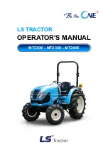
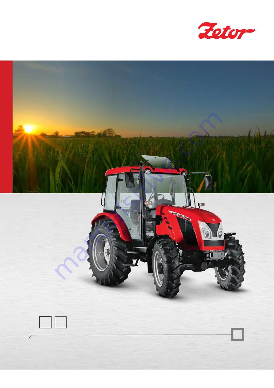
Страница 1: ...60 80 Tractor is Zetor Since 1946 OPERATOR S MANUAL MAJOR 01 2014...

Страница 2: ...a lot of new information and get a perfect overview of how to use the tractor with maximum efficiency during various kinds of work If you observe the rules of tractor operation and maintenance and dr...

Страница 3: ...2...

Страница 4: ...ng 22 Tyres and wheels 23 Short functional test 23 Acquaintance with the tractor 25 Safety cab 25 Opening doors from the outside 25 Opening doors from the inside 25 Rear window 26 Bottom rear window 2...

Страница 5: ...ctor 45 Hydrostatic steering failure warning signalization 45 Important notification 45 Running in the tractor 47 General principles of new tractor run in in first 100 hours of operation 47 In first 1...

Страница 6: ...front drive axle 67 Front wheels toe in 68 Adjustment of toe in of the wheels of the front driving axle 68 Front drive axle fenders 68 Rear wheel track change 69 Ballast weights 71 Ballast weights in...

Страница 7: ...eplacement 92 Checking the oil in gear box final drive housing and rear axle 92 Replacing oil filter element of hydraulic pump 93 Gear system drain plug 93 Oil replacement in gear system 93 Filling co...

Страница 8: ...Clearance circle and turning circle diameter 102 Index 103 CONTENTS 7...

Страница 9: ...NOTES 8...

Страница 10: ...rial number is impressed on a label situated at the top of the engine When ordering spare parts and within all written and oral communication always specify the data of your tractor that should be wri...

Страница 11: ...The right left front and back indications refer to the driving direction of the tractor NM13N082 LOCATION OF SERIAL NUMBERS 10...

Страница 12: ...g environment protection Or possibly sections describing handling of dangerous waste This symbol refers to optional tractor accessories installed by the manufacturer on the customer s request Accessor...

Страница 13: ...ust be connected with a latch z Driving downhill without an engaged gear is forbidden z Pay special attention when driving on a slope and muddy sandy icy or uneven ground z Observe the maximum set ang...

Страница 14: ...the tractor with parking brake before leaving tractor with running engine z Do not forget to brake the tractor with parking brake shift the gear remove the key from key switch and lock the cab before...

Страница 15: ...er the end of their service life you must observe relevant provisions of valid acts and implementation directives of these acts of the country where the tractor is used The last seller of the tractor...

Страница 16: ...with high concentrations of salt etc it is always necessary to clean the tractor thoroughly from chemically aggressive substances and neutralize them after the termination of the work according to th...

Страница 17: ...s I and II A category includes all tractors with set level of vibrations owing to similar specifications of construction Results of measurement on testing bench are listed in the following table pursu...

Страница 18: ...10 FOPS conditions Tractors ZETOR supplied already from production with front end loader are equipped with cab roof according to point 2 From safety reasons series ZETOR tractors supplied without fro...

Страница 19: ...observe special instructions related to accidents prevention and general rules related to technical safety la bour medicine labour hygiene and regulation defining operation on roads z The manufacturer...

Страница 20: ...Protective Structure Operator Protective Structure tested according to standards for forest machines Only forest superstructures approved by ZETOR TRACTORS can be mounted to ZETOR tractors In case of...

Страница 21: ...NOTES 20...

Страница 22: ...l gauge 1 is located on the left hand side of the engine Pull out the gauge 1 wipe it with a clean fibreless rag and slip it fully back in After pulling out the gauge once again check the oil level Th...

Страница 23: ...sure brakes is sufficient Hydraulic brakes of the trailer Check tightness of hygraulic brake circuits in the trailer and braking efficiency of the tractor with the trailer NM13N085 Check the condition...

Страница 24: ...value Check and if necessary retighten the bolts of the front and rear wheels Never drive with loose wheel bolts NM13N086 After starting the engine check whether the hydrostatic steering failure engin...

Страница 25: ...NOTES 24...

Страница 26: ...from the outside Right door of the cabin are equipped only with a button from the outside After unlocking and pressing the button of the lock the door opens by pulling the handle NM13N025 By pressing...

Страница 27: ...rear three point linkage and open rear window If there is collision we recommend working with a closed window NM13N027 For opening the bottom rear window it is necessary to push the lever 1 in the dir...

Страница 28: ...pictogram on seat s graiter C126 Release the lever 1 by turning in the direction of an arrow set the tilting of the steering wheel and lever 1 to be tightened by turning against the direction of an ar...

Страница 29: ...ing on the main lights in the grill of the bonnets by a switch 4 a side lights b dipped lights c headlights After pulling the switch lever 2 to the steering wheel acoustic horn is engaged Front windsc...

Страница 30: ...witch 5 is to position a after switching the switch to the first position the heating ventilator output is lower b after switching the switch to the second position the heating ventilator output is hi...

Страница 31: ...he brake system red It is on if air pressure in the trailer air brakes drops down under a critical limit 12 Indicator of hydrostatic control system failure red It is on if a failure occurs in the hydr...

Страница 32: ...ation in English is displayed in the top right corner COOLANT LEVEL Check and top up coolant in the equalizing tank AIRFILTER Carry out maintenance of the engine airfilter Shall such a situation arise...

Страница 33: ...2 foot brake pedals connected with a flap 3 foot fuel supply control pedal C127a Differential lockis controlled by a pedal placed on the right side of driver s seat Engaging differential lock is done...

Страница 34: ...ressed NM13N044 Gear shifting lever serves for change of gear box gear Gear shifting is done with clutch pedal depressed NM13N045 Road and reduced speeds shifting lever serves for shifting gear groups...

Страница 35: ...box revolutions are dependent on the engaged gear n neutral position b Independent revolutions of PTO shaft drive revolutions are dependent on engine revolutions Gear shifting is done with a tractor...

Страница 36: ...Fuel tank Fuel tank is located on the left side of the tractor A plastic tank with a volume of 80 litres is mounted as a standard Do not step on the tank NM13N089 ACQUAINTANCE WITH THE TRACTOR 35...

Страница 37: ...NOTES 36...

Страница 38: ...to idle run position 6 Switch the key of switch box from position 0 to position I Thermostart ignition control lights up Wait for the time when ignition control goes out the time is dependent on the...

Страница 39: ...ing temperature Never help a stopping tractor with a starter There is a danger of starter damage NM13N091 It is forbidden to start by short circuiting starter clamps Tractor is started only from drive...

Страница 40: ...wear and load damage Drive away with 1st gear to be used only when driving with a heavy trailer up the slope and in difficult terrain The engine control unit will automatically limit engine performanc...

Страница 41: ...speeds NM13N046 Gear shifting lever serves for changes of gear box gears Gear shifting is done with a depressed clutch pedal Only gears are shifted by main gear shifting lever the direction of travel...

Страница 42: ...t the gear shifting lever through neutral to lower gear Note For increasing the life cycle of synchrones it is possible to shift from higher to lower gear with the socalled double declutching NM13N058...

Страница 43: ...le with slip of rear wheels to increase pull of tractor On the road and on hard surface causes driving with front drive axle engaged increased tire wear of front wheels Permanent engagement of front d...

Страница 44: ...ure in the air brake system falls under a critical limit a red indicator on the dash board comes on In case the pressure in the air pressure system drops under a critical limit the indicator comes on...

Страница 45: ...kes to the function of hydraulics If there are shocks when foot brake pedals are depressed in the pipeline of hydraulic circuit it is necessary to bleed the hose from the brake valve to the quick coup...

Страница 46: ...ed with the manual brake If the tractor is on the slope wheels must be made stable with shims NM13N062 Hydrostatic steering pump failure is with pressure drop under 120 kPa behind the pump signalized...

Страница 47: ...NOTES 46...

Страница 48: ...g of the engine z Avoid excessive idle run operation z Check oil levels in engine often during this time increased oil consumption is normal z Check screw joints in particular in supporting parts of t...

Страница 49: ...NOTES 48...

Страница 50: ...f fatal injury if a chain pulls apart It is forbidden to use tractor axles individual travelling wheels such as reeling jack when rescuing a sunken tractor NM13N023 Serves for connecting double axle o...

Страница 51: ...in is signalled by the retracted indicator 3 see fig B After the attachment of the trailer you must always check whether the indicator 3 is retracted in accordance with fig B E304 The draw rod can tra...

Страница 52: ...ven by the maximum permitted speed of the slower vehicle of the set Tractor must be aggregated only with a tractor trailer for balancing tractor operation brakes or hydraulic brakes of trailer Static...

Страница 53: ...NOTES 52...

Страница 54: ...r in N neutral position 4 Connecting and disconnecting cardan shaft of aggregated machine to front PTO shaft of tractor to be done always only with engine at standstill and disengaged PTO shaft 5 Any...

Страница 55: ...tion clutch disengaged Lower position clutch engaged Rear PTO shaft is engaged with a lever 1 shaft drive placed on the left side of driver s seat Gear shifting is done with engine at standstill and e...

Страница 56: ...umber and the direction of PTO shaft revolutions is dependent on the shifted gear of reversing lever engaged speed gear and the group of gears engaged by reduction lever PTO shaft drive engagement lev...

Страница 57: ...asses Cardan shaft fro drive of these machines must be equipped with the socalled free wheel which ensures the disconnection of torque transmission with retroactive effect from the machine to tractor...

Страница 58: ...Mixed regulation fig 2 which is the combination of position and power regulation It is suitable mostly for tillage on lots with different soil resistance Power regulation fig 3 with which tools conne...

Страница 59: ...tting the speed of lowering three point linkage arms When turning the control of speed of three point linkage lowering in b direction the speed of three point linkage arms lowering decreases in a dire...

Страница 60: ...f three point linkage arms in transport position during transport If lowering speed control 3 is permitted and still a tool it cannot be lowered move the lever 2 to floating position c for a short tim...

Страница 61: ...sition at the end of a row Tool is returned back to working position by shifting the lever 2 to original setting External hydraulic circuit Extrernal hydraulic circuit control elements Supplies pressu...

Страница 62: ...locked Lever b is locked in this position 3 Pressure in quick coupler 3 Quick coupler 4 is connected with waste After release lever returns to position N 4 Pressure in quick coupler 4 Quick coupler 3...

Страница 63: ...ersing rotation hydro engine Reversing rotation hydro engine must be for function connected to quick couplers of one section When connecting hydro engines securing valves need to be included in both b...

Страница 64: ...upper draw bar hole 25 mm Category II Length of linkage axis 870 mm connecting balls holes of lower draw bars pursuant to ISO 28 mm of upper draw bar hole 25 mm NM13N053 Persons who are not charged w...

Страница 65: ...er draw bars The adjustment of left and right limiting draw bar is done by inserting a peg and to some of the holes b Both limiting draw bars must be mounted at all times NM13N054 Upper draw bar 1 is...

Страница 66: ...draw bars and automatically are locked in working position by means of locking pegs 1 Always check the position of slipped out end pieces and locking pegs see fig 3 E459 Both lower 3 and upper 4 draw...

Страница 67: ...NOTES 66...

Страница 68: ...always with any wheel track change or tire replacement with front drive axle Wheel stops with front drive axle must be set so that there would be a distance of at least 50 mm between front drive axle...

Страница 69: ...ymmetrically with both joints to keep the same lock of wheels to both sides do the measurement on the sides of rims z Locking nuts of heads of ball joints 2 tighten with a torque of 122 136 N Upper su...

Страница 70: ...hten the screws to a prescribed value after every release of foot joint z After travelling a distance of 100 m with an unloaded tractor retighten the joints again to a prescribed torque z After loadin...

Страница 71: ...NOTES 70...

Страница 72: ...weight kg 4 1 4x50 66 266 NM13N072 Combination of weights pcs Weights kg 4 4 8x30 240 All air locks of rear wheels are equipped with a valve which enables to fill air locks with liquid when using an...

Страница 73: ...same way Draining liquid from tires procedure E557 1 by heaving the tractor relieve tire and turn the wheel valve up A 2 let out air and unscrew the valve insertion turn the wheel valve down 3 remove...

Страница 74: ...t come in touch with metallic parts and electric installation The solution is nor harmful to the valve of air lock 5 Anti freezing solution prepared in the given composition must not be used in coolin...

Страница 75: ...NOTES 74...

Страница 76: ...out 1 minute because of storage of operation data During this time the supply of current from the accumulator must not be interrupted Do not disconnect the accumulator before this time expires Accumul...

Страница 77: ...mentally hazardous waste when buying a new accumulator hand the old one over to a seller who will dispose of it free of charge 7 Insufficiently charged battery can freeze in winter Alternator Alternat...

Страница 78: ...3N078 Pos Size of fuses Protected system 1 15A Direction lights 2 15A Brake lights 3 20A Ignition relay dashboard feeding start blocking recirculation 4 15A Headlights with control 5 15A Left side lig...

Страница 79: ...tion headlight beams must be parallel with longitudinal axis of tractor symmetry Perform the lights adjustment check with service weight of the tractor Front roof headlights can be used for operation...

Страница 80: ...nal drive housing A check of oil contents in the reducers and in the front driving axle housing A discharge of condensate from the air receiver A cleaning and smearing of accumulator battery clips wit...

Страница 81: ...r filter o o 1000 Safety cartridge replacement in the air filter o 2000 Filter cartridge replacement in the heater Every 1000 Eh or every 2 years Coolant renewal Every 2 years Oil renewal in the trans...

Страница 82: ...ended Service Fillings Tested on Zetor Tractors Oil to gear systems of tractors Oil for the front driving axle Viscosity Class SAE Performance Class API 10W 30 GL 4 Viscosity Class SAE Performance Cla...

Страница 83: ...of EN 590 Paraffin impurities or additional additives in fuel are not allowed for engines with Common Rail injection Manufacturer Oil labelling Classification Aral Vitam DE 32 HLP DIN 51524 Fuchs RENO...

Страница 84: ...axes bearings Position number Name Number of greasing points 1 Pivot pins 4 2 Spigot shaft 2 3 Cardan shaft joint 2 8P Number of position Name Number of greasing points 1 Rear semi axes bearings 2 2...

Страница 85: ...NOTES 84...

Страница 86: ...tion while the tractor is standing on a flat surface with the engine off The engine oil gauge 1 and the filling hole 2 are located on the left hand side of the engine Pull out the gauge 1 wipe it with...

Страница 87: ...r with a special tool a tightening moment of 15 17 Nm is required 6 Check tightness after the engine has started up NM14D008 The engine is equipped with two filling holes On the upper side of the engi...

Страница 88: ...cartridge 7 After the packing has sit down on the contact surface tighten up the filter manually 8 Attach the draining bolt 4 with the condensate level sensor 9 Plug in the cable of the condensate lev...

Страница 89: ...of the tractor and is accessible after the front bonnet has been lifted off Air filter maintenance shall be carried out once air filter pollution gets signalled Carry out the air filter maintenance a...

Страница 90: ...ust not vibrate after their mounting has been finished That after having closed the filter with the cover you must ensure a perfect tightness of the entire filter NM14D017 Inspect daily before startin...

Страница 91: ...tic steering tank 2 unscrew drain screw at the bottom of the tank 3 drain the oil 4 unscrew the nut of tank cap 5 demount the cap of hydrostatic steering tank NM14D019 6 remove and replace filter elem...

Страница 92: ...e oil heating in hydrostatic steering circuit Bleeding the Heating System Monitor oil level in the tank with all hydrostatic steering venting steps to prevent air sucking to the system of steering E72...

Страница 93: ...eze in the equalizing reservoir up to the upper mark labelled with MAX 8 Close up the equalizing reservoir with the overpressure plug 9 After having the engine warm up and the thermostat open let the...

Страница 94: ...f the new filter cartridge and screw on the cartridge 5 After the packing has sit down on the contact area tighten up the filter cartridge 3 manually 6 Check oil level in the transmission and top it u...

Страница 95: ...to figure 1 amount of oil inspection hole in the horizontal axis of a reducer after unscrewing control screw the level of oil must reach the brim of checking hole 2 filling oil hole at the top 3 drai...

Страница 96: ...rmful substances NM13N110 Air collector is placed on the right side of the tractor under the cab Draining the condensate from air collectorto be done by deviation of venting valve by pulling a ring Va...

Страница 97: ...tor for inflation A which fulfils the function of pressure equalizer tire filler and locking valve Screw a hose for tire inflation Screw the hose to the end of coil so that back valve will be compress...

Страница 98: ...rive belt A The belt gets stretched automatically NM14D002 If V belt tightness B is appropriate the belt sagging must be 5 5 mm while a force of 50 N is acting on the belt Stretch tight the V belt acc...

Страница 99: ...h adjustment nut 2 Free run of PTO shaft clutch control lever a must be 25 to 35 mm The track of lever between the lower lever position and the point when the control force on lever increases is the f...

Страница 100: ...ear PTO shaft height 725 Wheel base 2 210 Tractor s weight kg 3300 Type of tractor Major 60 Major 80 Type of engine TCD 2 9 L4 Design of engine serial upright water cooled Kind of engine injection fou...

Страница 101: ...25 8 4 000 20 3 500 30 2 300 Front tires steerability Travel speed km h 1 Maximum weight of set 8 5500 30 4300 Note Bearing capacity values apply for front wheel base of 1495 1525 mm and are in accord...

Страница 102: ...2300 170 3220 4000 170 480 70R30 2760 2300 160 3350 4000 160 13 6 R36 2140 2300 160 2600 4000 160 16 9 R30 2675 2300 160 3250 4000 160 Type of tractor Major 60 Major 80 Maximal lifting force at the e...

Страница 103: ...2460 rpm 51 Gear reduction Gear 540 1000 L 1 L 66 120 2 L 96 176 3 L 139 255 4 L 202 369 M 1 M 166 304 2 M 242 443 3 M 350 641 4 M 507 928 H 1 H 446 816 2 H 650 1190 3 H 941 1721 4 H 1362 2492 labell...

Страница 104: ...ont drive axle 94 Filling controlling and draining hole of oil of front wheels reducers 94 Filtration elements cleaning 95 Fire prevention principles 13 Fixed and free position of lower hydraulic draw...

Страница 105: ...ydraulic pump 93 Replacing the hoses of hydrostatic steering 91 Replacing the safety element of the air cleaner 88 Reversing lever 33 Road and reduced speeds shifting lever 33 Running in the tractor 4...

Страница 106: ...NOTES 105...

Страница 107: ...Operator s manual NEW MAJOR 60 NEW MAJOR 80 Edition 1 100 2014 Publication No 222 212 746 ZETOR TRACTORS a s Department of Technical Documentation Trnkova 111 628 00 Brno 106...

Страница 108: ...Made in EU www zetor com zetor zetor com...

Отзывы: