System Manual – MOVIDRIVE® compact Drive Inverters
149
3
1
2
3
4
5
6
7
8
9
10
11
12
13
14
15
16
17
18
19
20
21
22
Explanation of the parameters
Parameters
P75x Master-slave
function
The master-slave function allows for implementing automatic functions such as speed
synchronization, shared load and torque control (slave). A system bus interface (SC11
/ SC12) is used for the communication connection. To do so, make the following settings
for the slave: P100 Setpoint source = Master SBus. The process output data PO1 ...
PO3 (P870, P871, P872) are assigned automatically by the firmware. The programmed
terminal function "Slave free running" P60x Binary inputs basic unit / P61x Binary inputs
option gives operators the option to separate the slave from the reference input variable
of the master and switch to a local control mode.
*) DIØØ "/Controller inhibit" and the programmed binary inputs Enable, CW and CCW
must also get a "1" signal.
Connection check
In case of a communication link via SBus, P815 SBus timeout delay is effective. If P815
SBus timeout delay is set to '0,' there is no monitoring of data transmission via the SBus.
NOTE
Observe the following information when using a fieldbus:
The slave’s process data P87x is assigned automatically. They cannot be changed.
59990AEN
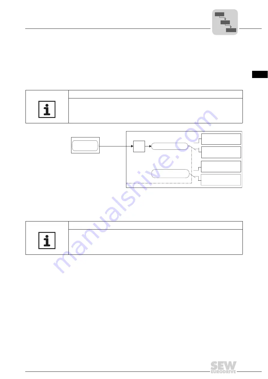
Figure 50: Master/slave function
Master
SBus
Slave
0
1
0
1
= Master SBus
P751
Scaling
slave setpoint
P750
Slave setpoint
Slave free running
P101 Control signal
source
P100 Setpoint source
= Bipolar setpoint /
Fixed setpoint
When P100 = Master,
Enable via master*
)
= Input terminals
NOTE
P814 SBus group address must be set to the same value for master and slave. The
bus terminating resistors must be activated at the physical start and end of the system
bus (S12 = ON).
P6..
P60.
P600
Summary of Contents for MOVIDRIVE compact MCH41A
Page 2: ...SEW EURODRIVE Driving the world...
Page 432: ......


