System Manual – MOVIDRIVE® compact Drive Inverters
173
3
1
2
3
4
5
6
7
8
9
10
11
12
13
14
15
16
17
18
19
20
21
22
Operating modes
Parameters
VFC 1 / 2 & Hoist /
VFC n-control &
Hoist
VFC n-control & hoist (only with MCV, MCH) in parameter set 1 only. Disabling 4Q
operation (P820) will be ignored.
In the VFC&Hoist operating mode, the start/stop speed (P300/P310) is set to the slip
speed of the motor; in the VFC n-control & hoist operating mode it is set to 15 1/min.
The minimum speed (P301/P311) is internally limited to 15 1/min in the VFC&Hoist
operating mode.
The hoist function automatically provides all functions necessary for operating an unbal-
anced hoist. In particular, monitoring functions are activated for safety reasons. These
may prevent the drive from starting: These are:
•
Monitoring the output current during the pre-magnetization phase.
•
Avoiding sag when the brake is released with load precontrol.
VFC 1 / 2 &
DC-BRAK.
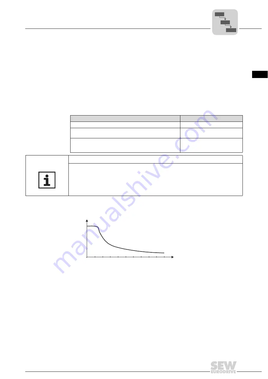
The DC braking function allows the asynchronous motor to be braked using a direct cur-
rent injection. The motor can be braked without braking resistor on the inverter.
A constant current with a rotating field frequency of 5 Hz is impressed during the braking
process. The braking torque = 0 at standstill. A greater braking torque acts at a slower
speed; the braking torque drops as the speed increases. The braking time and conse-
quently the duration of the braking current depends on the load connected to the motor.
DC braking is stopped once the rotating field frequency of the motor reaches 5 Hz and
the motor is stopped using the rapid stop ramp. The current is injected in line with the
rated motor current in accordance with the startup function. In all cases, the inverter lim-
its the current to max. 125%I
N
. For controlling the brake, see the braking function.
Faulty constellations
Triggered fault
2 or 3-phase motor phase failure
F82 = Output open
Premagnetization time too short or incorrect motor/inverter
combination.
F81 = Error start condition
Failure of a motor phase by active speed monitoring (factory
setting) P500 Speed monitoring 1 / 502 Speed monitoring 2,
P501 Deceleration time 1 / P503 Deceleration time 2
F08 = Error n-monitoring
NOTES
•
A single-phase motor phase failure cannot always be detected reliably.
•
SEW-EURODRIVE strongly recommends activating speed monitoring (factory set-
ting).
•
Correct performance of the hoist function requires the motor brake to be controlled
via the inverter.
02167BEN
Figure 53: DC braking: Braking torque profile
1
0
0
5 Hz
f
f
rated
M/
M
rated
P6..
P60.
P600
Summary of Contents for MOVIDRIVE compact MCH41A
Page 2: ...SEW EURODRIVE Driving the world...
Page 432: ......


